it's easypeasy - toss regular pot out , short pads for it's top and wiper ( so signal is going directly to buffer) , remove Jensen , solder appropriate AVC wires in place of Jensen
AVC being practically same as Jensen , just with zillion taps added
and AVC planned as pcb-xformer combo , with 20-something relays included
edit - , forgot to add - instead of pot , 24-position rotary switch in front , commanding with AVC relays
AVC being practically same as Jensen , just with zillion taps added
and AVC planned as pcb-xformer combo , with 20-something relays included
edit - , forgot to add - instead of pot , 24-position rotary switch in front , commanding with AVC relays
Last edited:

Dear ZM,
Any chance of a glimpse of the new shunt reg's schematic? I would like to try that.
Hope you are specifying parts that are easily available!
The relays you plan to use for the AVC - anything special about them? I am usually nervous about relays but wonder if there is a "good" one. I have found that battery power is a good idea for the coil.
If you are still using the 317 this might be a useful tidbit: http://www.waltjung.org/PDFs/Sources_101_P2.pdf
Adding that MOSFET makes a big difference.
Take care,
just relax ..... considering what type of power Papa is usually using (well - he and his boyz) , I'm much more hysteric about PSU
so , take it as notch above Papa's "good enough for task" approach ........ you can green, Papa can green ("let them waste time and energy,while I'm looking at Whales" ) , while I'm having peaceful sleep knowing that I overdone it , again
relays - usual industry thingies - something as Takamisawa RY24W-K ,jobbie with sealed gold contacts
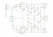
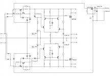
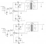
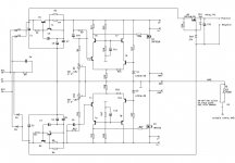
Good Gemini schematic as enclosed (NB- didn't check parts values ...... that step is always last one )
relay PSU - at least tjhose integrated on pcbs - ditto after the bridge in GG , taking positive and negative rails pre-reg .
that way , tiny relay current ( having 1 (SE pcb) and 1 or 3 relays (Bal pcb , 1 for Bal/Bal , 3 for SE/Bal operation) energized in any moment ) is taken equally from both rails , so both xformer windings still symmetrically loaded ....... while not influenting feeding of audio circuit
so - you see that I'm not of those thinking that color of LEDs is detriment to audio gadget performance
I did initially two Graetz approach ( so two secondaries , no CT) , but had impression that is just possible complication for regular cheapskate Greedy Boy , looking to use those surplus xformers from drawer (spitting image of Mighty ZM )
)
so , no soon trying it out - from two reasons - maybe it's too complicated (even if really simple) for making without proper pcb , and - again - I can't guarantee for all values in enclosed sch
will need several days more , after finalizing pcb files , to make proper sch documentation
funny - having subcircuits done , I don't need detailed schematics for process of final pcb construction - everything is going directly from head, in Eagle brd file .... removing wire bridges , going to two layers instead , connecting subcircuits , ading reg for relays , diodes for Bal/SE mode activating ...... bummer is that I'll need to translate all that to you guys .... even if I really don't need it
trivia : having opportunity to see some of Pa's sch/pcb file pairs , it's obvious that he also jumped ditto to pcb file , just looking at paper sketch .....
so , take it as notch above Papa's "good enough for task" approach ........ you can green, Papa can green ("let them waste time and energy,while I'm looking at Whales" ) , while I'm having peaceful sleep knowing that I overdone it , again
relays - usual industry thingies - something as Takamisawa RY24W-K ,jobbie with sealed gold contacts
Good Gemini schematic as enclosed (NB- didn't check parts values ...... that step is always last one )
relay PSU - at least tjhose integrated on pcbs - ditto after the bridge in GG , taking positive and negative rails pre-reg .
that way , tiny relay current ( having 1 (SE pcb) and 1 or 3 relays (Bal pcb , 1 for Bal/Bal , 3 for SE/Bal operation) energized in any moment ) is taken equally from both rails , so both xformer windings still symmetrically loaded ....... while not influenting feeding of audio circuit
so - you see that I'm not of those thinking that color of LEDs is detriment to audio gadget performance
I did initially two Graetz approach ( so two secondaries , no CT) , but had impression that is just possible complication for regular cheapskate Greedy Boy , looking to use those surplus xformers from drawer (spitting image of Mighty ZM
)so , no soon trying it out - from two reasons - maybe it's too complicated (even if really simple) for making without proper pcb , and - again - I can't guarantee for all values in enclosed sch
will need several days more , after finalizing pcb files , to make proper sch documentation
funny - having subcircuits done , I don't need detailed schematics for process of final pcb construction - everything is going directly from head, in Eagle brd file .... removing wire bridges , going to two layers instead , connecting subcircuits , ading reg for relays , diodes for Bal/SE mode activating ...... bummer is that I'll need to translate all that to you guys .... even if I really don't need it
trivia : having opportunity to see some of Pa's sch/pcb file pairs , it's obvious that he also jumped ditto to pcb file , just looking at paper sketch .....
Attachments

Last edited:
That definitely looks like something one should wait for the PCB!
At least, this one should wait for it. I will be patient.
Thanks for the glimpse. Though I would prefer to use two sets of rectifiers. The easy form of added complication.
I have no trouble believing you have all of this in your head.
I have the LED phobia, doesn't matter which color. They are used in plenty of places in circuits I am using so I guess I can live with them.
Looking forward to the boards becoming available. You know I want some.
bal pcb finished , and it seems I'm in a mood 🙂 , so will continue to finish SE pcb tonight
then , some blankin' da brain time , up to sorting parts values and names,sending them to 6L6 , producing proper schematics , sketches etc.
then , some blankin' da brain time , up to sorting parts values and names,sending them to 6L6 , producing proper schematics , sketches etc.
Attachments

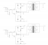
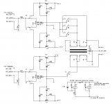
SE
SE , set of subcircuit schematics , almost finished
tonight , cross-checking nomenclature , and done
names and values not shown - just in case ..... to not confuse anyone (later)
SE , set of subcircuit schematics , almost finished
tonight , cross-checking nomenclature , and done
names and values not shown - just in case ..... to not confuse anyone (later)
Attachments
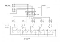
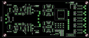
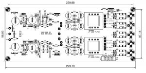
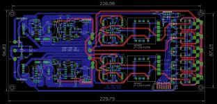
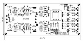
SE files done
sent to Jim
some of them attached here , for your plaisire
sent to Jim
some of them attached here , for your plaisire
Attachments
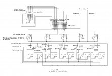

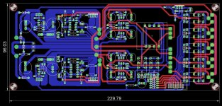
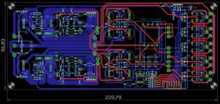
Bal files ,almost done
preliminary , so ...
still to check nomenclature , but most important is done - sch is married with brd file
preliminary , so ...
still to check nomenclature , but most important is done - sch is married with brd file
Attachments
Last edited:
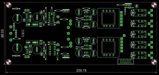
Golly. I'm slow today or something. Do you know how many times I looked at this before I realized and understood that the PCB with the 2 transformers is the SE?
😕😕😕
😱😱😱
😎😎😎
Again, awesome work, thanks again! This will be an amazing project!
😕😕😕
😱😱😱
😎😎😎
Again, awesome work, thanks again! This will be an amazing project!
yup
just a reminder (wrote that several times , also posted preliminary files simply to allow mellow grasping of things to come ) :
SE bard is stereo , one Jensen per channel ,connected as autoformer with 6db gain, logically;
Bal board is mono , one Jensen per channel ;
when used as converter - SE in/Bal out , gain is 6db overal (1V/V per phase ) , through balanced autoformer ;
when working in native mode Bal in/Bal out , having 6db gain overall , it's working as differential autoformer ,completely incidentally having SUSY* virtues
didn't tried/considered third mode - Bal in/SE out , but that's really trivial .......
*Tnx to Papa
just a reminder (wrote that several times , also posted preliminary files simply to allow mellow grasping of things to come
) :SE bard is stereo , one Jensen per channel ,connected as autoformer with 6db gain, logically;
Bal board is mono , one Jensen per channel ;
when used as converter - SE in/Bal out , gain is 6db overal (1V/V per phase ) , through balanced autoformer ;
when working in native mode Bal in/Bal out , having 6db gain overall , it's working as differential autoformer ,completely incidentally having SUSY* virtues
didn't tried/considered third mode - Bal in/SE out , but that's really trivial .......
*Tnx to Papa
Golly. I'm slow today or something........
hey
ya didn't confirm files downloading , as successful ?
didn't tried/considered third mode - Bal in/SE out , but that's really trivial .......
meaning, it will have 6dB too?
it'll be unity gain , but transformed from bal to SE
say 1V per phase input , giving 2V between phases , will give 2V at output (sole) phase
and you can choose which polarity you want
say 1V per phase input , giving 2V between phases , will give 2V at output (sole) phase
and you can choose which polarity you want
very nice! You have been busy 🙂 I like the SE/Bal functionality, why is the relais K7 a bit slower with the extra RC?
Last edited:
it'll be unity gain , but transformed from bal to SE
say 1V per phase input , giving 2V between phases , will give 2V at output (sole) phase
and you can choose which polarity you want
I have those voltages 🙂 Gain is always nice, mostly need a component between susy dac (ntd1) and my next amp project (vfet2).
I like that it still plays nice with other aleph related stuff. Win win
Thanks for bringing this project to a greedyboy diy level. 😀
very nice! You have been busy 🙂 I like the SE/Bal functionality, why is the relais K7 a bit slower with the extra RC?
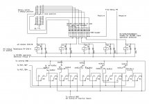
say that you need 2 inputs RCA , 3 inputs XLR:
-input 1 to RCA (relay K1) - short pins XLR1.1 and XLR1.3 ,mount and solder D21
-input 2 to RCA (relay K2) - short pins XLR2.1 and XLR2.3 ,mount and solder D22
when going to SE/Bal modus (selected either input 1 or input 2), this happens :
through D21 (D22) , both K6 and K7 are energized ; K6 being directly(no RC) connected , it will switch immediately (K6 section 1 and K6 section 2) , moving + buffer output to top** of positive dedicated winding of Jensen ;
in same time , same buffer output is still connected to mid point of positive dedicated winding of Jensen through K7 section 1, so upper part of same winding is effectively shorted for tiny amount of time ...... and , part of second later (when RC deliver) same K7s1 will release mid point from buffer's output
with same delay/same time as K7s1 - it'll release connection between negative buffer's output from belonging xformer winding (through K7s2) , thus avoiding now Dodo buffer(without modullation) to brake/pull to mud it's own winding ...... in same being modulated from positive winding ........
**- that way buffer modulating entire positive winding directly (gain 1V/V per phase ) , but also adjacent (negative) winding ...... doubling phases , so overall gain is 1: (1+1) [V/V] , so 6db overall
entire delay game is to avoid crackling sounds (remember - we are dealing with inductive thingies here) , when dealing with phase/gain switching
simply - I'm making make-before-brake action relays from normally brake-before-make ones ......
Last edited:
I have those voltages 🙂 Gain is always nice, mostly need a component between susy dac (ntd1) and my next amp project (vfet2).
....... 😀
NB that , when going in Bal , taking SE out (either pins 1(gnd) and 2 (hot) as normal/positive , or pins 1 (gnd) and 3 (hot) as negative phase) , we still have SUSY functioning .......
pretty clever ...... but I can't take any bloody credit for that ......... approach being explored and exploited from dawn of telephone era
dunno , need to check Pupin's patents** .......
edit: conclusion :
same as falling Apple (eating thingie , not brand) predates Newton , it's evident that SUSY predates Papa .........
further conclusion - Buddha is everywhere .......

**or any other , regarding xformer matrix-es
Last edited:
- Home
- Amplifiers
- Pass Labs
- What's wrong with the kiss, boy?