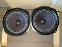
Last visit to my parent's house my father told me his speakers (Advent 25th anniversary edition) weren't working right, all he got was distortion. I pulled the grilles and sure enough, the foam woofer surrounds were shot. No surprise after 25 years or so.
The woofers came home with me. Refoam kits from Midwest Speaker repair arrived yesterday, and now they look as good as new. First time I have done this, but it's simple enough. I'll be heading down again tomorrow to reinstall them, and set up the new internet gateway that ATT sent him.
Bill
The woofers came home with me. Refoam kits from Midwest Speaker repair arrived yesterday, and now they look as good as new. First time I have done this, but it's simple enough. I'll be heading down again tomorrow to reinstall them, and set up the new internet gateway that ATT sent him.
Bill
Attachments
Nice work! I have a soft spot for those old Large Advents, they were my first "real" stereo speakers as a teenager.
Pass DIY Addict
Joined 2000
Paid Member
I was surprised that re-coning a pair of woofers was easier than I thought it would be. I did this for a pair of my father's speakers about 20 years ago.
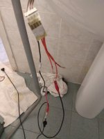
Today, I repaired one of the "power" sliding doors on the side of our Dodge Grand Caravan. As the sliding door opens and closes repeatedly, it flexes the bundle of wires that travels with the door. Eventually, the large-gauge wire that delivers power to the motor embedded in the door flexes too much breaks. At first, it gives an intermittent connection and then it stops working all together.
To properly repair this, you can't just resolder the wire in the middle. Doing so creates a rigid point along the length of wire that flexes each time the door opens and closes. So, your repair will only last a few months before it breaks again - right next to the solder joint.
Instead, you have to remove the entire length of wire that flexes as the door slides, and insert a new length of wire, making solder joints as close to the fixed ends of the wire harness (where the wire doesn't flex as the door moves) as you can.
Now the door operates as it should again. It's a simple fix, but takes a while to get access to the parts that you need in order for the repair to last.
I had channel drop out intermittently on a new build. A channel would cut out, then you tap the preamp and it came back.
Ended up being a bad Omron relay of all things. Replaced it with Phoenix Contact and all is well now.
Ended up being a bad Omron relay of all things. Replaced it with Phoenix Contact and all is well now.
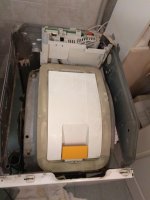
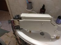
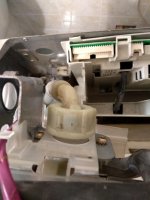
My Miele washing machine.
Attachments
Last edited:
Fixed a software bug in a model train DCC controller.
I changed the software to control accessories too.
To make sure the power was always there I used a null data packet to waggle the power to the rails when no loco's were selected.
Sent off the chip to the buyer.
Built up another pcb and tested it and train no longer moved.
Took a while to find but the null packet (0,0,0) should have been (255,0,255) and (0,0,0) is in fact an "all stop" control.
Serves me right for not fully testing previous version of software.
More haste, less speed.
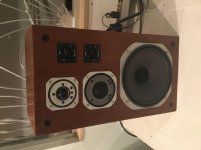
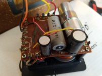
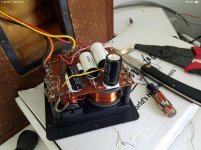
Rebuilt the xo’s in the NS670’s I scored about a month ago for $100
Listening right now and gotta say the difference is quite noticeable to the better.....I thought they imaged well before, now it’s almost freaky....the separation between the instruments and even vocals. quite a enveloping speaker.
Here’s the crossover before and after....
Listening right now and gotta say the difference is quite noticeable to the better.....I thought they imaged well before, now it’s almost freaky....the separation between the instruments and even vocals. quite a enveloping speaker.
Here’s the crossover before and after....
Attachments
My Miele washing machine.
I've never owned a German washing machine. How much "because we can" engineering is there in it?
I've never owned a German washing machine. How much "because we can" engineering is there in it?
My grandad worked in Germany, he used to fly Lancasters.
One of my church customers has an older electronic organ that's had an intermittent note for going on 2 years now. During that time they've called me twice about it, only to call back before we could schedule to say, "Never mind - it's working again." This winter it finally went dead and stayed dead, so I did the 1-1/2 hr. drive up there today to take a swing at it.
Finally remembered to snap a coupla pics this time! Get a load of this silly crap:

These are called Gate boards. This group is for the organ's bass pedals. 32 daughter boards, one for each pedal. Musical pitches of various octaves & waveshapes enter from the backplane via the protruding resistor tails. They are then gated on & off via a single 12VDC pedal gate voltage, with appropriate attack/decay constants applied. The audio outputs are collected onto the buss wires in groups of 6. The problem of course is that the whole thing is soldered together in one big solid block of sadness.
After locating the board with the dead pitch (I have virtually no schematics for this thing), I decided to chop loose the functioning board directly behind it, so I could at least have some room to probe the defective board in-circuit. I'd wedged down the problem bass pedal before I even removed the organ's back cover, so I'd know immediately if the dead note came back to life during disassembly. By some miracle, it actually stayed dead throughout the process of removing the adjacent board (power temporarily removed of course), and only came back when I was right on top of the action! How often does that happen!
I soon discovered that I could flex the bottom corner of the board and make the note come & go. From there it was a simple matter to find a resistor lead in a through hole that had functioned for 40-some years without a drop of solder on the pad. These boards were clearly hand-soldered, and this one pad just got skipped. Monday morning or Friday afternoon? Who knows, but it was sure satisfying to sit there for a minute with a spudge stick and play "Shave and a Haircut" on that loose resistor lead!
Anyway, I forgot to take a "before" pic, but here's the "after":

Now comes the fun part. I was prepared for a nightmare of trial & error, trying to get all those stupid little resistor tails lined up just right to go through the holes in the backplane. Amazingly, it took only a couple of tweaks before the whole thing just slotted right into place! Holy cow. Had a bit more trouble spudging those dual ground buss wires (along the bottom) back through the board holes, but not too bad really.
Capped off the drive home by almost skidding into the ditch in a snowstorm. Key word being "almost." Whew!
Finally remembered to snap a coupla pics this time! Get a load of this silly crap:
These are called Gate boards. This group is for the organ's bass pedals. 32 daughter boards, one for each pedal. Musical pitches of various octaves & waveshapes enter from the backplane via the protruding resistor tails. They are then gated on & off via a single 12VDC pedal gate voltage, with appropriate attack/decay constants applied. The audio outputs are collected onto the buss wires in groups of 6. The problem of course is that the whole thing is soldered together in one big solid block of sadness.
After locating the board with the dead pitch (I have virtually no schematics for this thing), I decided to chop loose the functioning board directly behind it, so I could at least have some room to probe the defective board in-circuit. I'd wedged down the problem bass pedal before I even removed the organ's back cover, so I'd know immediately if the dead note came back to life during disassembly. By some miracle, it actually stayed dead throughout the process of removing the adjacent board (power temporarily removed of course), and only came back when I was right on top of the action! How often does that happen!
I soon discovered that I could flex the bottom corner of the board and make the note come & go. From there it was a simple matter to find a resistor lead in a through hole that had functioned for 40-some years without a drop of solder on the pad. These boards were clearly hand-soldered, and this one pad just got skipped. Monday morning or Friday afternoon? Who knows, but it was sure satisfying to sit there for a minute with a spudge stick and play "Shave and a Haircut" on that loose resistor lead!
Anyway, I forgot to take a "before" pic, but here's the "after":
Now comes the fun part. I was prepared for a nightmare of trial & error, trying to get all those stupid little resistor tails lined up just right to go through the holes in the backplane. Amazingly, it took only a couple of tweaks before the whole thing just slotted right into place! Holy cow. Had a bit more trouble spudging those dual ground buss wires (along the bottom) back through the board holes, but not too bad really.
Capped off the drive home by almost skidding into the ditch in a snowstorm. Key word being "almost." Whew!
Last edited:
Very cool- reminds me of working on modular mixing consoles, though this is probably a tad simpler. It's that whole repeated circuit thing.
Yes! Now that you mention it, this does remind me of those nasty little Kelsey mixers we used to sell at the music store back in the day. Never understood all the fuss over those things.
Eliminated an oscillation from a phono preamp by replacing the twisted pair with shielded 2C cable.
I HATE working with this wire! It's insulation is stiff and hard to strip, it's stranded and the twists don't stay put so you need to tin the ends anyway. But the oscillation is gone so well worth the toil.
This also goes to show that using a 12V 20A SMPS marketed for lighting up LEDs can make a quiet phono amp. Sure there's some noise but it's lower than the surface noise of a new record. 50$ for the entire power supply for a phono, line/HP, and buffer. I just paid 66$ for a 100VA 20VCT transformer to run the same boost converter in a quest for lower noise only to fix it with wire. We'll see how much less hum there is with a linear supply anyway as an excercise.
Last edited:
I used to hate screened wire.
As I soldered the screen it would also melt the inner wire and short out on the screen !
As I soldered the screen it would also melt the inner wire and short out on the screen !
Just got done fixing the last of the busted water pipes from the deep freeze in Texas. One in the bathroom in the house, and 2 out in the shop.
I used to hate screened wire.
As I soldered the screen it would also melt the inner wire and short out on the screen !
For RF and test equipment, I am just using "crimp".
Mentioned elsewise that I fixed a Pioneer TX-9500 receiver -- the tantalum output caps were shot -- this happened rather suddenly. Great receiver.
Wondering whether to invest time fixing a space heater thermostat or just get a new one.
The thermostat in my heater is junk. 750W setting comes on and stays on or it doesn't come on long enough, and on the 1500W setting it turns off well before it should no matter where you set the control.
I'm considering using a temperature controlled outlet for it instead. Maybe you could do that instead of fixing the internal one. Just jump it out 🙂
I'm considering using a temperature controlled outlet for it instead. Maybe you could do that instead of fixing the internal one. Just jump it out 🙂
A new model railway shuttle I built.
Didnt power up and flash LED.
12 volts at input. 12volts at regulator.
5 volts at regulator out.
No 5 volts at micro.
Failed to solder regulator out pin to smd pad. Both other pins were soldered ok.
Jolly bad show chaps.
Didnt power up and flash LED.
12 volts at input. 12volts at regulator.
5 volts at regulator out.
No 5 volts at micro.
Failed to solder regulator out pin to smd pad. Both other pins were soldered ok.
Jolly bad show chaps.
Last repairs:
I own 3 Waldorf synths from circa 2000.
All developed same syndrom rotating encoders doing what they want...
So i had to change them:
Microwave Xt: 45
MicroQ: 7
Pulse+: 6
Of course it doesn't happened as planed: i pulled an smd diode on microQ. Being smd no marking and Waldorf being Waldorf no schematic availlable... used a 1n4148 and it worked.
I changed display on MWXT too as i get bored with the greenish colour which started to fade away anyway. Now it have blue eyes ( better in the color scheme too as it is orange). The knobs get changed too as rubber gone sticky over years and i was wise enough to buy the models used on the last iteration some 10y ago. Brand new and good for next 20 years.
Pulse+ seems to have other issues with digital chip in charge of controllers. Will have to find someone able to fix it as i am not...
Please don't talk to me about changing any more rotary encoders for the next 10 years! Looks like an overdose. 😀
Last edited:
A Sinking Office Chair.
Found it in the street. Broken of course, the gas cylinder is broken, so it's too low. 😕
Easy fix. Google. Found some discarded PVC pipe over the road at the house renovation. Cut a 2" piece.
How to Fix a Sinking Desk Chair: 11 Steps (with Pictures)
A £100 chair for nothing:
Full Lumbar 3 Lever Operator Chair With Adjustable Arms - Furniture At Work(R)
Sitting on it now. 😎
- Home
- Member Areas
- The Lounge
- What did you last repair?