Last week I repaired an old (1980's perhaps) Musical Fidelity Dr. Thomas amp. Not the little bitty one that you can easily find images of on line, but a big, beefy 19" wide job that weighs about 40lbs. It was gifted to me 2 years ago by a friend who bought it on ebay and had his purchase price refunded because of the obvious shipping damage (it had obviously been dropped in transport). The fuse holder was sheared off. Some binding posts were bent. But the scariest part was that is sounded like there were loose parts inside - big ones!
Opening up the amp wasn't easy because many of the 3mm Allen key pan head screws that held the case to the chassis were stripped and some were frozen. An hour or so with a Dremel and an easy-out tool got the case apart. The toroidal power transformer (a big one) was not attached to anything. Worse - there was no hole in chassis to screw-mount the transformer to! Turning the amp over I found the remains of 4 tie-wraps that are supposed to hold the toroid to the amp. The filter caps were more or less the same story, held to the amp with tie-wraps. This was not a ham fisted repair job, that was how the amp was designed!!!
Once I rebuilt what should have been done in the first place, I replaced the fuse holder, straightened out the binding posts, reattached the bridge rectifier (also loose), redressed some wire bundles that were messy, retouched a few solder joints that looked suspect, and tightened a zillion screws (that amp has more screws than I've ever seen in an amp).
After slowly bringing up the AC voltage and no smoke detected I realized that I no longer have a set of passive crossover equipped speakers that I could test the amp with (I have some small desktop jobs, but they couldn't handle the ~150W this amp is capable of). So off to the shed to pull out the remains of some party speakers that are sort-of OK (good enough to act as a load, anyways). The amp worked surprisingly well considering the banging around it got. I'll probably use it somewhere, just don't know where yet.
Last month I repaired/restored a Mosrite 500 amp. Serial # 003. Also had a chance to talk w/ Ed Sanner, the design guru of the Mosrites.
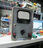
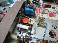
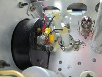
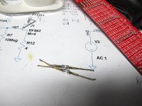
Today I repaired an HP400D purchased a few years back from a ham radio guy. It wasn't expensive. The input capacitor was leaky and the mica on the input way out of spec. One of the 6CB6's was weak and replaced. 1uF/400V meter capacitors replaced. The early silicon diodes were way off spec, one measurng Vf of 1.6V, the other 4.4V.
Why a panel meter in this era of digital -- it can monitor the output of my THD analyzer and tell me how much I am heading in the correct or wrong direction with the adjustments.
Works great!
Why a panel meter in this era of digital -- it can monitor the output of my THD analyzer and tell me how much I am heading in the correct or wrong direction with the adjustments.
Works great!
Attachments
Looks good. Too bad about the diodes, they have a nice vintage look. What's up with those caps? They replaced cans?
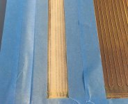
This morning I repaired a pair of Magnepan MG-1b speakers that had been languishing for years. Fortunately only the tweeters needed a full rewire (the wire as nearly dust) and one woofer had a break right at the end which is now repaired with a good old lineman's splice and solder. Acetone and glue is mostly all it takes.
Pics are:
Tweeter section cleaned down to mylar.
3M 77 spray glue
32 gauge tweeter wires glued on.
Pics are:
Tweeter section cleaned down to mylar.
3M 77 spray glue
32 gauge tweeter wires glued on.
Attachments
Been designing a transistor matcher.
It wasnt working right so made a few changes to a second pcb to try to fix it.
Powered it up and the processor wouldnt run or program.
Buzzed out the circuit and it was fine.
Resoldered SMD processor in case it was that but no difference.
PCB looked fine so tried a different processor, same problem.
Tried programming the processor but kept getting a JTAG error which I have never had before.
Clearly something wrong with the pcb.
Put the scope on all the processor pins and one looked a bit odd so unsoldered resistor feeding power to it and processor burst into life.
It seems the pin was being driven into overvoltage and the JTAG check on power up was seeing this and stopping processor running.
I checked over pcb to see if any components were wrong
For some reason any 3k3 resistors were swapped with 20k resistors.
Looks like resistors had been put back in wrong bags, not sure if it was me or they came that way.
The op amp feeding the processor was outputting 9 volts in stead of 3.3 volts and upsetting the processor. The resistor should have limited it but obviously not enough.
So sorted now but definitely a challenge and kept me out of mischief all afternoon.
That's a pretty big difference in resistor values Nigel! I check every resistor with the multimeter before installing. That's mainly because I'm colour blind so can't use the colour codes (on resistors that have them). But I think I would have noticed the difference between orange orange and red black 😉
I guess the lesson is, don't trust what it says on the bag!
Tony.
I guess the lesson is, don't trust what it says on the bag!
Tony.
What's up with those caps? They replaced cans?
The originals were 1uF/400V paper -- they had 16AWG leads!!! -- were probably the most significant issue. The input cap -- 10nF was also a 10nF/600V paper and leaky.
It is too bad about the original rectifiers -- I started out when we had to solder diodes and transistors with an alligator clip so they wouldn't destroy themselves.
Aside from color blindness, it has gotten harder to read modern resistors. The grey body makes it harder to tell the difference between red and orange. Older dark brown was easier to read.
The knock sensor in my car. At first, it did not affect the normal driving of my vehicle, but I felt that the vehicle vibrated significantly and the fuel consumption also increased. To save money I decided to detect and repair by myself, and fortunately I did it!😀
I have to say this post helped me a lot, so I want to share with you guys if anyone has encountered the same problem as I did.
I have to say this post helped me a lot, so I want to share with you guys if anyone has encountered the same problem as I did.
Nice work Pano! I'm guessing you will get a lot of enjoyment out of this repair!!
Thanks Tony. The repair was fun, and the speakers sound very nice. I actually got them in trade a couple of years ago from a friend. He found them at the Goodwill thrift shop!
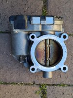
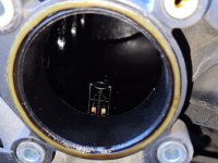
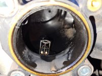
My wifes car. Engine light had been on more than off. Fault code suggested that the problem was map or mas airflow readings being out of wack.
Pulled off the throttle body which was gunked up as was a sensor just behind it. Cleaned with mas airflow sensor cleaner and cleared the codes and seems to be good now.
Seems a bit more responsive. Hopefully fuel economy should improve as well.
Tony.
Pulled off the throttle body which was gunked up as was a sensor just behind it. Cleaned with mas airflow sensor cleaner and cleared the codes and seems to be good now.
Seems a bit more responsive. Hopefully fuel economy should improve as well.
Tony.
Attachments

 you would pay big money to have something like that looked at by a dealer.
Thanks Mooly, from what I could find looking up the fault codes, many people have spent over $1000 getting sensors replaced and it still didn't fix the problem, and in the end a clean of the throttle body did. Apparently it is also a common dealer practice to replace the whole throttle body, which would be a rather expensive excercise I would think since it is a fly by wire type!
Tony.
Tony.
Been designing a transistor matcher and curve tracer.
Had a few problems with accuracy on pnp side as the source pin is related to 9 volts and not zero volts so some changing signals from 0-9 to 9-0 was involved. The 0-9 comes from a pwm signal from a processor which is 0-3.3v so a times 3 (approx) to get it to 9 volts.
So far so good.
Then I noticed that the pnp side had a kink in its curve that shouldnt be there.
I scoped it and sure enough there is a kink in the curve.
Couldnt work out why so did a ltspice sim of a n channel mosfet driven from a variable source. The sim ran just fine. So more head scratching.
I though perhaps my differential amplifiers which read the drain voltage were loading it so changed 10k to 100k. Still not fixed.
I then noticed it was working ok, but when I looked at my setup a gate wire had dropped off the n channel mosfet.
It then suddenly click the problem is only there when n and p channel mosfets are connected up at the same time. Oddly the n channel works fine with both connected.
I drew out the circuit and what is happening is both mosfets are fed from a variable power source. However, both mosfets gates are driven at the same time which pushes current back into the variable power supply and upsetting the p channel readings.
My variable power supply comes from a npn transistor so it will push volts out but will also allow current back into the supply causing an over voltage.
The variable power supply needs to be push pull to work properly.
Took all day to find the problem.
I know of one mechanic with a reputation for doing that. It started to make sense when a friend of mine took her classic '69 LTD in for a carburettor rebuild and it came back running like a dog. We learned later that he was amassing a yard of wrecked cars so he could play lego with parts.wintermute said:Apparently it is also a common dealer practice to replace the whole throttle body
- Home
- Member Areas
- The Lounge
- What did you last repair?