Errata List:
Input Voltage Clarifications
In the Maximum Ratings table, Maximum V DS is specified at 200 V. For applications purposes, the main input DC supply voltage
should be limited to 160 V DC . For transient operation between 160 V and 200 V, please contact EPC at Steve.Colino@epc-co.com
Input Voltage Clarifications
In the Maximum Ratings table, Maximum V DS is specified at 200 V. For applications purposes, the main input DC supply voltage
should be limited to 160 V DC . For transient operation between 160 V and 200 V, please contact EPC at Steve.Colino@epc-co.com
May I use your ucd-orig_sinus_ucd+_verzija1.asc for testing? I then go include mine hd shaper and such, only I need to include a delay of 100 nS in your sim file, you now how.
thanks./
No problem..
but you can enter manually the delay... in RCD area (this trigger blocks).. try right click on some elements to see what can you change and tune.
+1 for Sure AA-AB32313 (MkII) + Meanwell.
Is there a link to the translation of the German site where comment is made about a number of Class ads. I've built eight Ds and sold seven. One more to build.
Is there a link to the translation of the German site where comment is made about a number of Class ads. I've built eight Ds and sold seven. One more to build.
I'm sorry, I've read the quoted post and the post quoted by that one but it's still not clear to me which site you mean. If you could point me to the text (or copy & paste it here), I'd translate it for you.
No problem..
but you can enter manually the delay... in RCD area (this trigger blocks).. try right click on some elements to see what can you change and tune.
Thanks, I had already found it.
It sims more quick indeed, see nocely the effects from deadtimes.
regards
I'm sorry, I've read the quoted post and the post quoted by that one but it's still not clear to me which site you mean. If you could point me to the text (or copy & paste it here), I'd translate it for you.
Thanks. It is this shootout of Ds which were rated.
DIY-HIFI-Forum - Einzelnen Beitrag anzeigen - Abletec Diy digital Audio Class D
Last edited:
I did use the sim model from Grizlek, it is nice to see what dead time does, what I need to now is the calculation of the low pass, because I get other outcomes, I think I need to now how to use the impedances, like 8 ohms and the amp side who is very low, or am I wrong.
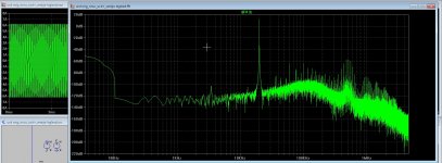
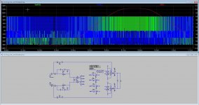
Here some pictures with lag lead, for fase shift self oscillating, a bessel bandpass can work nicely, then there is maybe more stability.
I have tested with very high input square and sinusoidal. I do see however much spourious signals in sim, maybe I have setup something wrong in ltspice.
In the meantime mine circlotron is started again, making a board, so class D is just some fun, for now because I do go make one.
regards
Attachments
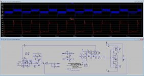
What is bandwidth of this amplifier, I mean can you put sine 20 khz at the input to see what is phase shift/ delay at the output..
Now this seems quite stable, hmm maybe putting RC low pass at the input to about 25 kHz would reduce this instability even more. But it seems to be outside audio range hmm (the overshoot)
Now this seems quite stable, hmm maybe putting RC low pass at the input to about 25 kHz would reduce this instability even more. But it seems to be outside audio range hmm (the overshoot)
Last edited:
How high it will go? That depends - like on every class D amp - on the load impedance. Yes, the output inductance interacts with the load and that got strong influence on that matter.
Well this one did give the lowest distortions, the lag lead version do work, but critical poles are needed.
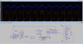
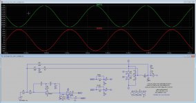
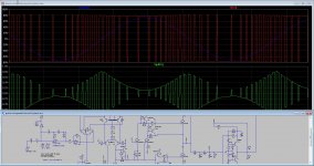
Here I did sim the fase shift from 1 Khz, 10 Khz and 20 Khz, 1 Khz did not give much but 10 did and 20 even more, think that it is some digital shift, the schemtic looks like a kind of analog delta sigma, distortions are very low in sim, do not now in real, I go try some day. for overshoots, a coil do not like squares, maybe some overshoot happens in the fase shift, the fase sift network maybe, try a bessel one there, and yes I have also did a pre and post feedback, I do not like post, and so do use only pre.
The idea of this schematic is not mine, it is a idea seen on the internet and just change some parts. there is a lot of people who work on class d and most of the ideas are already invented, except the real digital pad, I do not go, I am diy, not a professor.
Do someone now waht the distortions between brackeds in total hamrnic distortions, is that the noise or imd.?
regards
Attachments

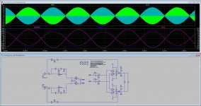
Bridge version, in clip, uge trouble.
and the same in distortions. but uge shoot through.
what do I need to change in the switches for full bridge? need I double models of SK1 and SK2 also, because I have two more.
nice such much fun. thanks.
and the same in distortions. but uge shoot through.
what do I need to change in the switches for full bridge? need I double models of SK1 and SK2 also, because I have two more.
nice such much fun. thanks.
Attachments
Well I find it why the problems occur, did wrong with the switches, K2 K1, I did name K2 K4 etc, but Grizlek did use this two models by remame the switches I presume.
oke, It work, however copy the switches did make dead time wrong, 8 Kw
oke, It work, however copy the switches did make dead time wrong, 8 Kw
Attachments

How high it will go? That depends - like on every class D amp - on the load impedance. Yes, the output inductance interacts with the load and that got strong influence on that matter.
Load impedance should be inside feedback loop so that its effects are dimished. I mean feedback should work that way, at least it does on Brunos UCD from "patent"
Well this one did give the lowest distortions, the lag lead version do work, but critical poles are needed. <snip>
Put square at imput 1khz and make modulation at least 80 %, this should start to oscillate at completely different freq.
This method seems to be superior to all of them.. but is not stable, transistor network needed ( I posted image from some other forum member). But I never tried it. 🙂
What is benefit of bridge version ?
Last edited:
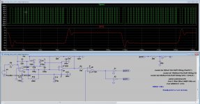
Maybe a discrete hysteric window see last picture, it keeps frequency stable.. All ucd amps do drop osc frequency when reaching the rails. ot get the unstability from the error amp?
Question I get big uge shootthrough here, I do something wrong with that full bridge ucd. it is quite tricky to do it right.
was a test, and no not Kw but Ka.
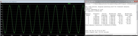
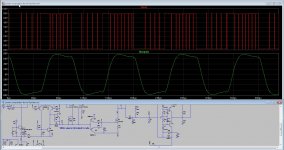
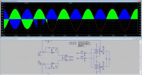
pictures a test with a window, it keeps things stable in sinusoidal signals, even when touching supply rails.
The ringing was due to the filter, this one is much better, coils do not like squares.
regards
Question I get big uge shootthrough here, I do something wrong with that full bridge ucd. it is quite tricky to do it right.
was a test, and no not Kw but Ka.
pictures a test with a window, it keeps things stable in sinusoidal signals, even when touching supply rails.
The ringing was due to the filter, this one is much better, coils do not like squares.
regards
Attachments

Last edited:
anyone try the crown xps 1502 power amp? or carver c-4000 pre amp / and c-500 amp . or the carver tfm 35 x?
Maybe a discrete hysteric window see last picture, <snip>
What this hysteretic windows does ? It seems like pre filter and post filter feedback?
This type of feedback is your idea or based on some paper also ?
What this hysteretic windows does ? It seems like pre filter and post filter feedback?
This type of feedback is your idea or based on some paper also ?
Hi
it is from a paper, this idea, I think reinvent the wheel is not needed here, the window does prevent shift down of the carrier when driven hard I did read there.
https://www.google.nl/url?sa=t&rct=...hp?id=253790&usg=AOvVaw29BD2LA3BSvJo25iW8L9AH
There is very much already invented for class D not much new ideas to do except the delta sigma and full digitall ones, so we combine and optim1ze.. Phillips came with the UCD amp also
and diy people did make it better, not Phillips
it is just a setup test it needs more afcouse, hysteric windows can anso made simpeler then the discrete one. I am not a electronic calculator, brain is somewhat smaller here.
regards
Last edited:
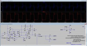
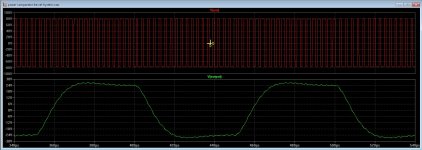
I do see a shift in frequency between input and output, this due to the switching and demodulation behavior, like also happens in digital stuff, it is not a problem, but when i need feedback from the output I get trouble with stability, so, we need a delay in the feedback line, a bessel allpass can work, or a output bessel filter made such that delay is corrected.
For ucd amps it is more easy, what I do talking about is a full bridge with a triangle generator, these are more stable because the carrier stays on his place when drive hard.
Grizlek, I did made the ful bridge, no shoot through, even without a dead time delay, I think the switches are lossless, the delay of the comparator was already enough.
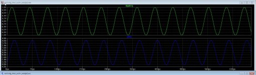
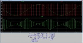
When drive hard I see the switching stops for the negative side, maybe it is normal, strange is output signal stays intact, last picture you see the fase shift between input and output, do feedback that way we get maybe trouble, I get because it do not work properly. Delaying the triangle do afcouse I think not work.
Only last picture has triangle in open loop, I did try the feedback, I go try current feedback, I like that more. First two are self oscillation versions.
regards
kees
For ucd amps it is more easy, what I do talking about is a full bridge with a triangle generator, these are more stable because the carrier stays on his place when drive hard.
Grizlek, I did made the ful bridge, no shoot through, even without a dead time delay, I think the switches are lossless, the delay of the comparator was already enough.
When drive hard I see the switching stops for the negative side, maybe it is normal, strange is output signal stays intact, last picture you see the fase shift between input and output, do feedback that way we get maybe trouble, I get because it do not work properly. Delaying the triangle do afcouse I think not work.
Only last picture has triangle in open loop, I did try the feedback, I go try current feedback, I like that more. First two are self oscillation versions.
regards
kees
Attachments

Last edited:
- Home
- Amplifiers
- Class D
- What Class-D amp give best sound?