jfetter,
Electrical conduction is well understood and carbon is especially well studied because of its high practical significance. Maybe you are not acquainted with the subject.
MarcelvdG,
What specifically do you disagree with and why?
Electrical conduction is well understood and carbon is especially well studied because of its high practical significance. Maybe you are not acquainted with the subject.
MarcelvdG,
What specifically do you disagree with and why?
I do not subscribe to any of the theories that have been propagated.
To which theory are you a believer?
To which theory are you a believer?
Hello All,
Bruce Hofer of Audio Precision has some good recommendations for minimizing circuit noise and distortion. Take a look at the download document below and search for:
“Resistor Voltage Coefficient Effects”
“Resistor Temperature Coefficient Effects”
https://www.ap.com/download/designi...itUSh4ggygNfkpyQRZ6a5kVtYDckWA5HjR1GqUT0sIktA
The goal is to get the resistor distortion low enough that it is buried deep in the real noise floor. The noise is real, large FFT bins and averaging will reduce the noise on you FFT plot letting the distortion harmonics peak above the apparent noise floor. FFT’s do not show the real noise floor.
Thanks DT
Thanks. That's something I have suspected for a long time, but never had the time/resources/will to confirm.
Tia effect has been observed in old tube circuits using CC resistors exclusively for decades.
Tia effect has been observed in old tube circuits using CC resistors exclusively for decades.
Now decades later, amplifiers with thin film on chip resistors are performing at 0.0000x % THD+N.
That is single digit PPM performance.
On the third image notice how the third harmonic distortion increases as frequency decreases. Also note there is not much change in the second harmonic for a two octave change in frequency.
As expected, in general, but it is nice to see it quantified.
See for added info attached from Vishay. Note that they have it wrong a bit about the wirewound, but it is never easy to counter a competitor especially when he is as good as you are ;-)
Also note that they stole fig 3 & 4 from Scotts' app note AN-348 - fig 4 & 5 ;-).
Jan
Attachments
Last edited:
And you are a troll, but what has that got to do with anything?
Marcel, your ignore list is your friend ;-)
Jan
Three curves showing resistor distortion. Using my bridge technique the fundamental of 0 level is suppressed.
First a good Dale RN65 resistor, second an Ohmite 1/2 watt carbon composition type and finally the effect frequency .....
This is a interesting simple test. I do not have an AP but if I take several identical same batch configured in series maybe can reproduce it with my set-up, -145db.
What is your bridge technique?
I'm thinking of a bake first then normalize temperature for tests.
Would make interesting white paper.
-
- yes, usual metal-film resistors have that signal-dependent noise about several uV/V or lower (it depends), good ones - have less than 1 uV/V. But composite ones - more than 10 uV/V. Such noise sometimes is controlled by manufacturers and present in datasheets.When idle, all resistors are made equal, they just generate thermal noise, but when a carb-comp resistor is subjected to an AC signal, it generates an excess noise proportional to the instantaneous amplitude of the signal, smearing and widening the original spectral line.
Beautiful demonstration, also showing that crappy resistors and potentiometers have an influence extending on the signal further than just their basic non-linearity
Last edited:
MarcelvdG,
What specifically do you disagree with and why?
Looking at post #78, I don't see anything that could help Jan getting to understand the physical background of resistor distortion, nor getting to know the magnitude of resistor distortion, nor helping someone else to come up with the right answers. Meanwhile you are quite impolite to both simon7000 and Leon Chua. Hence my conclusion that you are a troll, or at least behave like one.
That said, I do agree with you that memristors are unlikely to have anything to do with resistor distortion. A memristor is a network element that as far as I know has no physical counterpart, so it is unlikely to play a role in anything physical.
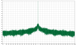
I modelled resistor excess current noise, multipling a pure bin-centered sine with an 1+x factor, x being a low-level pink noise.[...], but when a carb-comp resistor is subjected to an AC signal, it generates an excess noise proportional to the instantaneous amplitude of the signal, smearing and widening the original spectral line
It turns out that the resulting spectral line is still exactly one bin wide but the noise floor around the line is elevated. Zooming in, one can see that the noise skirt actually has a wing shape, very close to the test frequency levels drop to the value present at very low frequencies.
Attachments

You know practical pink noise is band-limited at low frequencies? That's why you see the wing shape.
If pink noise were not thus band-limited it would have infinite power. Perhaps you can tweak your simulation to have more (or less) LF bandwidth to confirm if this is the explanation.
In physical systems we start to talk about drift and aging when the frequency of 1/f noise is very low. There's no limit to the DC-offset in an infinite stream of 1/f noise.
Hello All,
I looked back at the threads from a couple of years ago, same same same.
Ed,
You need to do some noise measurements and show us that the distortion you are measuring is buried in the noise floor. Or not? Tell us about all the other resistors in your bridge. How is it that only the resistor (Rt) under test is the only source of the "measured" distortion?
Jan,
Take a look at this Youtube video. Foil resistors have a distortion peak at low mid-range frequencies even with a otherwise low PPM temco.
YouTube
I am going to sit out for awhile.
DT
MarcelvdG,
I did clearly specify uncontaminated, homogeneous, low density carbon as the least damaging resistor material for the transmission of the audio signal. This could be elaborated of course, but facts do not convince anyone anyway, especially from an untrusted source.
Homogeneous materials do not generate spikes. Not even resistors made of dispersive materials generate large spikes. Noise is not generated by signals, but to various degrees, it has a harmful impact on the signal. Noise is not at all the worst distortion caused by resistors. Amplifiers can be dead quiet with carbon composition resistors. LTspice simulations provide deception rather than insight.
Memristor and flux-linkage are terms in a frivolous and unacknowledged approach.
Last edited:
Jan,
Take a look at this Youtube video. Foil resistors have a distortion peak at low mid-range frequencies even with a otherwise low PPM temco.
YouTube
DT
Yes, I know that video, I actually once attended an in-the-flesh presentation of this by Mr. Hofer.
Work is going to be done to characterize that low to midrange distortion. Watch this space ;-)
Jan
My immediate thought was the description "cemented onto a substrate" - could this distortion be as simple as dielectric absorption into the cement? Thin and thick film resistors use a ceramic substrate directly, such as alumina, which has extremely good properties as an insulator. As the DC properties of metal foil are exceptional it got to be a reversible temperary change giving the distortion.Take a look at this Youtube video. Foil resistors have a distortion peak at low mid-range frequencies even with a otherwise low PPM temco.
YouTube
I also suspect the distortion in metal foil is much lower than thick film anyway, just notably for its incongruity with the DC specs.
Great video BTW, not enough views yet!
Confirmed. When I steeply high-pass the noise multiplier data at 100Hz the "wing center" get wider, exactly 100Hz to either side of the spectral line and the slope follows the highpass-slope. Interesting property of this kind of noise modulation I wasn't aware of, thanks again.You know practical pink noise is band-limited at low frequencies? That's why you see the wing shape.
If pink noise were not thus band-limited it would have infinite power. Perhaps you can tweak your simulation to have more (or less) LF bandwidth to confirm if this is the explanation.
I am assuming that at AC instead of DC, this changed R due to the same power dissipation with be less than at DC because the R will start to cool before the end situation. In other words, the resistance will be modulated but the 'depth', if you will, the difference between the two values of no dissipation and the given dissipation will be less than at DC.
Jan
I agree. However, it can be verified by simulating the system. Furthermore, nonlinearitis depend not only on the heat source (due to temp. dependent resistivity) but also on the temperature dependence of other thermophisical properties of the involved materials like thermal conductivity and specific heat. Moreover, the convective and radiative heat transfer mechanisms at the solid-air interface (for example) is nonlinearly temperature dependent and will contribute to the non linearity of the system.
Very interesting thread.
- Home
- Design & Build
- Parts
- What causes resistor distortion?