General question are RN55C10R0F and RN55C10R0FB14 the same/interchangeable? They only have RN55C10R0FB14 at Mouser

Thank you for this, I ordered the parts I needed. I hope I didn't ruin the PCB or anything. Thanks for everyone's help so farIt's just different packaging, it looks like.
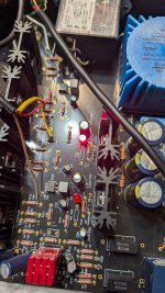
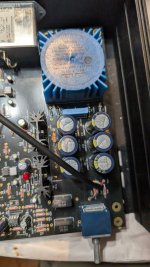
Okay, update....it's working! But the sound is very "crunchy" or distorted. I replaced everything you guys said I should and looked around for things that may be burnt, couldn't find anything off but I'm sure there is something. I replaced the LEDs as well. I turned it on and 1 lit up. Where do I go from here? Sorry if this is a bad pic.
Attachments
Last edited:
A few of the resistors adjacent to the fets look discolored from heat. I'd check them all. C10 does look like it may be bulged. The ground signal connection looks grungy, it wouldn't hurt to resolder that. Also, I see that R10 and R14 are still in place. Remove them or remove the LED's and install R9 and R13.
I would take the Burson V6 out until you've confirmed it's all working, use a 5532 or similar cheap alternative until you know everything is OK. Killing a 1 euro chip doesn't hurt as much as killing a 50 euro op-amp.
I am on it!A few of the resistors adjacent to the fets look discolored from heat. I'd check them all. C10 does look like it may be bulged. The ground signal connection looks grungy, it wouldn't hurt to resolder that. Also, I see that R10 and R14 are still in place. Remove them or remove the LED's and install R9 and R13.
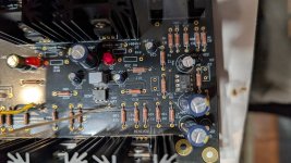
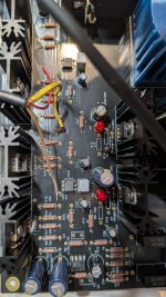
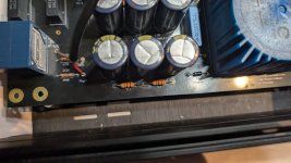
Removed c10 and replaced it, removed R10 and R14
Sorry about the photos it auto FOVs. So I took multiple pictures
Sorry about the photos it auto FOVs. So I took multiple pictures
Attachments
Last edited:
Hey I'm sorry, but could you explain more on how to do this?Not sure if you've checked this already or not but make sure the body of the potentiometer is grounded. With the board out of the case, try running a shorting wire between GND and the mounting ring/nut of the pot, even momentarily to see if the crackling noise goes away.
It comes up now and again in this thread but see if this post (#3414) helps clarify. Do you have input gnd connected directly to IEC gnd? It's not clear from your pictures but just some things to troubleshoot through (or refer back to 6L6's build pictures in the first post).
If you have a cheaper opamp (5532, LM4562), I would try that instead of the expensive ones until you're sure everything is working properly. Depending on what rail voltages you configured, the amp is also likely going to have too much voltage for your MUSES02 in the long run. There are mods to mitigate this but I don't recall the details offhand. Again, those details will be buried in this thread but the forum search and google will help set you in the right direction if you want to look into it.
If you have a cheaper opamp (5532, LM4562), I would try that instead of the expensive ones until you're sure everything is working properly. Depending on what rail voltages you configured, the amp is also likely going to have too much voltage for your MUSES02 in the long run. There are mods to mitigate this but I don't recall the details offhand. Again, those details will be buried in this thread but the forum search and google will help set you in the right direction if you want to look into it.
@1nfinity, I just read through some of the previous posts as I didn't realize you had actually built this WHAMMY and had it running back in 2023. If that's the case, your problem isn't likely an ungrounded pot but can you confirm that you've had it running for 2 years with the 4N35 backwards?
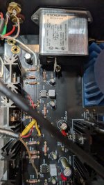
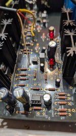
Given the overheated resistors, I would suspect the FQP3P20 has potentially sustained some injury on the problematic channel. Do you have a (cheapie) component tester to check it with? You'll have to desolder it from the board to test it unfortunately.
Given the overheated resistors, I would suspect the FQP3P20 has potentially sustained some injury on the problematic channel. Do you have a (cheapie) component tester to check it with? You'll have to desolder it from the board to test it unfortunately.
Hey I don't have a component tester but I can get one and I can check it out@1nfinity, I just read through some of the previous posts as I didn't realize you had actually built this WHAMMY and had it running back in 2023. If that's the case, your problem isn't likely an ungrounded pot but can you confirm that you've had it running for 2 years with the 4N35 backwards?
Given the overheated resistors, I would suspect the FQP3P20 has potentially sustained some injury on the problematic channel. Do you have a (cheapie) component tester to check it with? You'll have to desolder it from the board to test it unfortunately.
Sorry I didn't confirm this and I thought I did. Yes I had it running for 2 years with the 4n35 Backwards2 years with the 4N35 backwards?
Forgot to ask. How big of a heatsink would i realistically need if the output stage will be run on +-12V and 15 ohm bias resistors? No longer have access to the drive that had the LTSPCIE simulation.
Almost ordered the pcbs with the wrong mosfet pinout.
Almost ordered the pcbs with the wrong mosfet pinout.
Last edited:
So basically, that is not possible without damage occurring, let alone decent sound.Sorry I didn't confirm this and I thought I did. Yes I had it running for 2 years with the 4n35 Backwards
Is it possible that i damaged the entire thing and would need a new PCB and parts to actually fix it?So basically, that is not possible without damage occurring, let alone decent sound.
- Home
- Amplifiers
- Pass Labs
- "WHAMMY" Pass DIY headphone amp guide