No, remove R10 and R14. There 3 ways of configuring the regulators and you have 2 versions combined. If you are using the LED's do not stuff R9, R10, R13, R14.
Don't feel bad! I edited it after you posted, because it was unclear: Check at the input to D1/D2 and D3/D4, which is the side near the transformer. Then I'd check the output voltage, too, on the other side of the diodes. Note that the transformer output is an AC voltage. So (I think) is what's coming out of the diodes, though it is a funny looking wave.I feel terrible because I am not sure how to do that either, could you explain it to me? (how to check the output of the transformer)
Right. So says the build guide, though not the schematic I have.No, remove R10 and R14. There 3 ways of configuring the regulators and you have 2 versions combined. If you are using the LED's do not stuff R9, R10, R13, R14.
@1nfinity
With your DMM set to DC volts, 200V if not autoranging,
put the black lead on ground, the input wire’s shielding near the pot is a decent spot,
then with the red probe,
tell us the voltage at the line side (cathode) of D7
and the not line (anode) side of D8.
This will measure the unregulated PSU.
With your DMM set to DC volts, 200V if not autoranging,
put the black lead on ground, the input wire’s shielding near the pot is a decent spot,
then with the red probe,
tell us the voltage at the line side (cathode) of D7
and the not line (anode) side of D8.
This will measure the unregulated PSU.
It gave me -0.34. leaving it unplugged (turned off), correct?@1nfinity
With your DMM set to DC volts, 200V if not autoranging,
put the black lead on ground, the input wire’s shielding near the pot is a decent spot,
then with the red probe,
tell us the voltage at the line side (cathode) of D7
and the not line (anode) side of D8.
This will measure the unregulated PSU.
Okie dokie I did, and I was getting -0.90 to -0.91Turn it on please.
🙂 🙂 🙂
I will remove it once I am able to (once 6l6 has me going through things) I think I am getting overwhelmed with all the things to do and check lol one thing at a timeNo, remove R10 and R14. There 3 ways of configuring the regulators and you have 2 versions combined. If you are using the LED's do not stuff R9, R10, R13, R14.

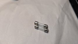
Both look great!Unplug from the wall and remove and check the fuse.
Attachments
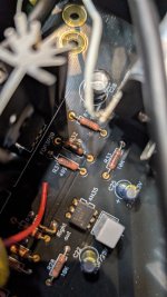
I think it would be good to take some in focus close up views of the bottom of the board. Seems like you could have some possible cold solder joints just looking at the top pics. I guess if it was working for a while, then it's unlikely a solder joint gave way.

You're getting that on both sides? I.e., both at D7 and at D8? Or is that just at D8?Okie dokie I did, and I was getting -0.90 to -0.91
Both look great!
With your DMM on continuity mode (“beep”), verify the fuses are intact. They can look fine and be blown.
I heard beeps on bothWith your DMM on continuity mode (“beep”), verify the fuses are intact. They can look fine and be blown.
Sorry, I haven't done this yet but I can try it nowYou're getting that on both sides? I.e., both at D7 and at D8? Or is that just at D8?
So I did this and the only thing that's getting anything is D2. Away I am getting D1 at 4.76 and D4 4.14Don't feel bad! I edited it after you posted, because it was unclear: Check at the input to D1/D2 and D3/D4, which is the side near the transformer. Then I'd check the output voltage, too, on the other side of the diodes. Note that the transformer output is an AC voltage. So (I think) is what's coming out of the diodes, though it is a funny looking wave.
I heard beeps on both
Ok, good.
Put your fuses back in the fuse holder if you haven’t,
Set DMM to AC volts,
With power on, carefully read voltage at the AC pads near the back of the transformer, where the AC from the power inlet module attaches to the PCB.
Okay, I would but, r32 started smoking. It scared me so I turned it offOk, good.
Put your fuses back in the fuse holder if you haven’t,
Set DMM to AC volts,
With power on, carefully read voltage at the AC pads near the back of the transformer, where the AC from the power inlet module attaches to the PCB
Attachments
Okay, I would but, r32 started smoking. It scared me so I turned it off
replace what is burned
obtain new optocoupler, mount it properly
check the other one
see post 5452, 5460
Hi 1nfinity, it appears that the opto-isolator is still backwards. R32 is in the circuit that controls the opto.
Gotcha, gonna order the parts and replace itreplace what is burned
obtain new optocoupler, mount it properly
check the other one
see post 5452, 5460
- Home
- Amplifiers
- Pass Labs
- "WHAMMY" Pass DIY headphone amp guide