Only curious but I'll ask. The two red LEDS on the board. Are either of them lit? And what two points are you measuring voltage from? Yup, it matters.
Others are better informed than I am, but what I'd suggest is checking the voltage at other points along the way, to try to isolate the problem. Check the DC voltage coming out of the rectifier on both sides. So this would be at R20 and R21, or at the proper end of D1 and D2. Check the schematic for which end you want in each case. Then you might check the input to the voltage regulators, though that may not be very different, and I suppose you might as well check between R20/37 and R21/38. I'm going to guess it's one of the regulators....So I opened it, sorry for the delay in doing that. I was able to get the meter out and check and it said -10 or -17 something like that with the amp turned on. I wasn't getting +17V and on the other check I was only getting -10v. So, it seems like it's a PSU problem? What parts exactly do I need to change?

I used the testing method in the tutorial. I test C9 and ground near the pot. I did R13 and R14 too. No LEDs are onOnly curious but I'll ask. The two red LEDS on the board. Are either of them lit? And what two points are you measuring voltage from? Yup, it matters.
You will have to take out the PCB and check everything in order. First the secondary of the transformer, then the diode bridge, then the resistors in the CRC, then the negative voltage regulator, the LEDs if you use them, all in order. Failure of the capacitors is also not ruled out, although this is less likely because the device is not old.So I opened it, sorry for the delay in doing that. I was able to get the meter out and check and it said -10 or -17 something like that with the amp turned on. I wasn't getting +17V and on the other check I was only getting -10v. So, it seems like it's a PSU problem? What parts exactly do I need to change?
Here are some I hope will help@1nfinity Please post a series of well-lit, in-focus photos of your whammy, it will be extremely helpful for the troubleshooting process
Attachments
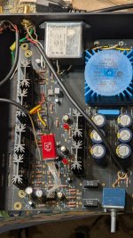
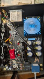
Are these current photos? The last one is showing broken connection(s) at the output wiring...
That opamp arrangement looks like an oscillation factory. Did you check whether the output was generating RF?
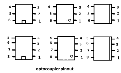
I can only see 1 of the opto isolators but is it in backwards? Should the line be closer to the transistors?
Yes this is current photosAre these current photos? The last one is showing broken connection(s) at the output wiring...
I did not, how can I test that?That opamp arrangement looks like an oscillation factory. Did you check whether the output was generating RF?
1Infinity, according to this build pic from 6L6 at least 1 of your opto's is in backwards.I can only see 1 of the opto isolators but is it in backwards? Should the line be closer to the transistors?
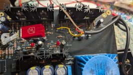
R32 is burnt up, so something was trying to send a lot of current to the negative rail.
As @ZUM911 noticed, the 4N35 that’s visible in the photo is installed backwards.
The Burson on the fly leads isn’t helping the anything, but may not be the culprit.
If the LED are out, there’s no power to the regulators, so the PSU needs to be probed and determined where the loss is.
What is the raw supply measuring?
I am still new to building this stuff so I'm sorry, but could you guide me on how to measure the raw supply?R32 is burnt up, so something was trying to send a lot of current to the negative rail.
As @ZUM911 noticed, the 4N35 that’s visible in the photo is installed backwards.
The Burson on the fly leads isn’t helping the anything, but may not be the culprit.
If the LED are out, there’s no power to the regulators, so the PSU needs to be probed and determined where the loss is.
What is the raw supply measuring?
He means check the output of the transformer (at the input to D1/D2 and D3/D4)). And then you might check what's coming out of D1/D4 and D2/D3.
Isn't it R9 and R13 (not installed) that you're meant to omit with the LEDs?The LED's and R10, R14 installed. Remove the resistors.
So remove the LED's, R10 and R14 and test it?The LED's and R10, R14 installed. Remove the resistors.
I feel terrible because I am not sure how to do that either, could you explain it to me? (how to check the output of the transformer)He means check the output of the transformer. And then you might check what's coming out of D1/D4 and D2/D3.
the 4N35 that’s visible in the photo is installed backwards.
huh?
edit: got it, zum posted pic of proper while pics in #5446 are showing flipped opto, at least that one close to IEC
Attachments
- Home
- Amplifiers
- Pass Labs
- "WHAMMY" Pass DIY headphone amp guide