No, the board is fine. Likely most of the components are fine. There’s probably a doohickey or two that are burnt up, but most everything else will be completely fine.

I have done worse than that many times, and I don't remember ever damaging a circuit board. I have seen some that were damaged, but the current had to be great enough to actually burn the board black. In other words, it was quite obvious. You have not even come close to this sort of thing.
Yes I had it running for 2 years with the 4n35 Backwards
then just buy new kit and build it again
as a penance

frame existing one and put on the wall, as friendly reminder
my workshop is wallpapered with specimens of my stupidity
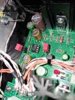
If the two 10 Ohm resistors in the output stage and the four 5.1 Ohm resistors in the power supply are enough (resistance in total) perhaps the output devices survived the lack of bias control (from the opto in backwards)? Perhaps there is enough resistance that the output devices, transformer and fuse all survived the error?
Did you probe the output devices (on the bad channel) and do they look ok?
Did you probe the output devices (on the bad channel) and do they look ok?
1nfinity is going to be going down that road next. At the moment he is waiting for a meter? We'll see where this leads.
Hi @Mooly, back to the imbalance issue, since then I have tried shorting the two channels to force mono - and this does solve the issue. I have swapped out the pot for another Alps from Parts-Express (both 50K and 20K) but I still get the same issue - left channel being louder than right. The imbalance is especially prevalent when listening to very low volumes - in which the only left channel can be heard and nothing coming from the right.Measuring resistance isn't a reliable check surprisingly (and its not always accurate when done in circuit anyway) because it is the ratio of the two gangs that matters rather than absolute values.
To get an audible difference implies a large imbalance is happening somewhere. Just link the pins and test.
Another very good test if you have not got a scope and generator is to apply a low DC voltage to both inputs (say a 1.5 volt battery) and measure the DC voltage at the pot wiper which should be identical for both channels. Measure between the wipers and rotate the pot and you should always see zero volts DC if both track identically. Any voltage that appears is due to imbalance.
Any value from 10k to 100k will work but 10 or 20k are probably preferred. A lower value does load the source more but any modern kit has no issues with those values.
Linear pots tend to track better than log and its dead easy to fake a log law with the addition of one resistor.
See 'changing the law of a pot'
https://sound-au.com/pots.htm
Do you have any other suggestion to fix this issue? Don't think I want to spend more $ on trying out more pots. I'm thinking to simply lower the gain in half as most of my listening is at low volumes. How will I cut the gain in half?
-Max
It is best to adjust the voltage gain of the amp so normal listening level is about 1-2 o'clock at pot.
The Alps are not very good at the low level setting. If you buy a lot it is possible to "hand select" the best (expensive solution).
But you can measure the pot you have (before it is connected) to test the balance/imbalance using maybe 2 x DMM in Ohm setting. This to be sure the pot is the problem?
Maybe it is possible to "adjust" one of the pot channels to match the other by means of an external resistor?
Edit: the last suggestion was without thinking at all.......
Edit: Nelson Pass uses 2 x monopots to overcome such problem (I have read that somewhere).
Edit: If the pot is the problem an attenuator with precision resistors like Goldpoint etc. could be an option.
Last edited:
back to the imbalance issue, since then I have tried shorting the two channels to force mono - and this does solve the issue. I have swapped out the pot for another Alps from Parts-Express (both 50K and 20K) but I still get the same issue - left channel being louder than right.
As a sanity check if you still have the old pot it would be worth measuring it out of circuit.
Turn it to minimum just as if it were in the amp and then turn it up a little by about the same amount of rotation you would be using when the the worst imbalance occurs. Now measure the resistance on each gang as follows.
From middle leg to one of the end legs. Note the result down.
From middle leg to other end leg. Note the result down.
From end to end. Note the result down.
Do the same for the other gang. So that is six readings. When you measure make sure your fingers are not touching the probes or pins at that will alter the result. Lets see what the imbalance is.
Do you have any other suggestion to fix this issue?
Make 100% sure these parts are correct in value (I think we did this but check). Differences in some of the resistor values (actual incorrect values, not tolerance) could interact with the pot and give an apparent gain difference. Unlikely but check.
Do you have any other suggestion to fix this issue
Don't use a log pot 🙂 They are often terrible for channel balance. Use a linear pot and fake the log law with the addition of a single resistor if you wish which goes from wiper to ground.
The values of R3&R5 - 100k should be checked. Last time I got (from Mouser) a Dale RN55D, one piece 100k and one 82k marked 100k. Since they are in parallel with the potentiometer slide for the AC signal, they may affect the channel balance slightly.
Yeah I've just been a little busy but I'll be back on it soon. I got the meter just gotta desolder....well I forget what to desolder and test1nfinity is going to be going down that road next. At the moment he is waiting for a meter? We'll see where this leads.
I played around with various opamps, and came back to the Muses 02. Somehow that one fits best with the Whammy. Yes, the Burson V7 Classic sounds a little better, but that opamp heats up like crazy at +/-15V, so it's not my first choice. The box is closed, I'm afraid of what will happen in the summer when the temperatures rise. At @mikorist Whammy 68pF compensation was needed for Muses, here 33pF is enough. Obviously it behaves differently with Toshiba mosfets .I rarely use headphones, but it's great as a Line preamp, and that's how it'll be used mostly. I think I closed the box for some longer period of time. 😁
Of the important changes compared to the original schematic, I have:
1. R1/R12 - 2k2 (lover voltage gain: 3,15x)
2. C26/C27 - 100uF 16V bipolar (Nichicon ES MUSE) for a lower cut-off frequency: 0.7Hz -3dB (original 7Hz -3dB)
3. C12/C17/C22/C25 22uF 16V bipolar (Nichicon ES MUSE)
4. C2/C7 - 33pF (Wima PP) for Muses 02 opamp
5. Without C1/C5, signal cable connected directly to R2/R7 and GND
6. Output DC protection by @miro1360
7. Mute assembly
8. 7815ACTG & 7915ACTG voltage regulators
(R16/R22/R29/R32 - 10ohm Dale RN60D, everything else Dale RN55D)
Attachments
Last edited:
When C1/C5 1uF are not used (DC connection) , you can expect a small change in the DC offset at the output depending on the used opamp (fet/bipolar inputs) and the value of the potentiometer. Specifically for 100k pot and Muses 02 DC offset changes from 0.7mV to 4mV with potentiometer rotation. It is in principle negligible, and with fet inputs opamap is less, and with a smaller value potentiometer it is also less.
What I noticed with the Burson opamps is the large DC offset. Specifically, with the V6 classic and V7 classic, it starts from 20mV when switched on and then drops to around 8-10mV. The small trimmer is available on all of them for adjustment, but on the V6 it is closed and inaccessible from the outside without opening it, and on the V7 it is available, but removing the small white sticker seems to void the warranty. DC offset adjustment is tricky, it's small trimmer and very sensitive to the slightest movement, but it can be adjusted to +/-1mV when warmed up.
What I noticed with the Burson opamps is the large DC offset. Specifically, with the V6 classic and V7 classic, it starts from 20mV when switched on and then drops to around 8-10mV. The small trimmer is available on all of them for adjustment, but on the V6 it is closed and inaccessible from the outside without opening it, and on the V7 it is available, but removing the small white sticker seems to void the warranty. DC offset adjustment is tricky, it's small trimmer and very sensitive to the slightest movement, but it can be adjusted to +/-1mV when warmed up.
Last edited:
I've been rebuilding a Whammy I bought used from the bay of fleas - should have built one fresh but you live and learn, but have a new board in it now with Sparkos regulators, an Evotronix Saligny mosfet regulator and I was plannnig on MUSES02 op amps, which I've not tried yet. I've got Burson V7 vivids already and in a Lehmann amp they sound quite full with a forward mid compared to a 2134, which I'm not keen on for a headphone amp, so I'm hoping the 02 will add to the 2134 sound with a touch of bass and sound slightly more open, that would be ideal. I've got 100pF comp caps in at the moment but I've not finished building yet, I'll keep your mods in mind, many thanks !
The Muses 02 certainly sounds more open than the OPA2134. I don't have them, but I expect that. The NE5532 Signetics, bought second-hand from the Chinese, has a good bass, but it is murkier for me at high frequencies. The OPA2604 also has a lot of bass. The Sparkos SS3602 has a very, even overly open sound in Whammy.
As for the compensation of various opamps, as I already said, without a generator and an oscilloscope there is no way to do it.
As for the compensation of various opamps, as I already said, without a generator and an oscilloscope there is no way to do it.
From the small technical details, I would add that plastic spacers of 1mm should be placed under the heatsink (on the soldering pins), so that the heatsinks do not touch the PCB. The probability of accidentally breaking through the insulating varnish is small, but it still exists.
Ofc i ordered the wrong capacitors and only noticed it after lcsc shipped notification. Well my only choice is using two 22UF caps back to back but then don't know if the reduced capacitance will do anything funky.
I've tried using non-polar caps and I'm not sure I could hear a difference - there may be a difference but my hearing might not be up to detecting it, or at least not in the circuits I tried them in. I use Audio Note electrolytics and they sound very good to start with and are also very consistent. I am going to try Audio Note tantalum non magnetic resisters, but the cost even in the UK is high, each one is about £6 or $8 and that's for the smallest, if you want 1w for greater stability it's 4x that, per resister ! Then there's the silver tants ....
tantalum non magnetic resisters
but you must!!!!
they're made of Praeputium!!!

The BOM calls for bipolar caps so i would use those. But from the looks of it the circuit works with normal caps as well.I've tried using non-polar caps and I'm not sure I could hear a difference
- Home
- Amplifiers
- Pass Labs
- "WHAMMY" Pass DIY headphone amp guide