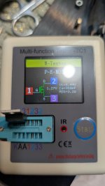
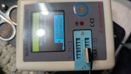
Hey! I'm back again and i desoldered the FQP3P20 (both of them) and here are the pictures from the tester. First picture should be the FQP3P20 closer to the op amps and the second is the one closer to the RCA@1nfinity, I just read through some of the previous posts as I didn't realize you had actually built this WHAMMY and had it running back in 2023. If that's the case, your problem isn't likely an ungrounded pot but can you confirm that you've had it running for 2 years with the 4N35 backwards?
Given the overheated resistors, I would suspect the FQP3P20 has potentially sustained some injury on the problematic channel. Do you have a (cheapie) component tester to check it with? You'll have to desolder it from the board to test it unfortunately.
Attachments


Could you point me towards those please?Ok, what about the regulators?
I tested using a multi meter 7815 says 0.85 and 7915 says .08 (hope I did that right, I feel dumb)7815 and 7915, middle of the PCB, near the red LEDs.
Meter to DC volts, black probe on ground, measure with red probe,
7815 pin 3 should be about 17V,
7915 pin 3 should read around -17V
7815 pin 3 should be about 17V,
7915 pin 3 should read around -17V
Should I solder back in the FQP3P20 and turn it on to test? I put the black probe on ground (next to the pot) and red on the left bit, should I be putting it on all 3 of the "legs" Gate, Drain or SourceMeter to DC volts, black probe on ground, measure with red probe,
7815 pin 3 should be about 17V,
7915 pin 3 should read around -17V
Should I solder back in the FQP3P20 and turn it on to test?
No.
I put the black probe on ground (next to the pot)
Good.
and red on the left bit,
???

should I be putting it on all 3 of the "legs"
Never ever.
Gate, Drain or Source
They are Integrated Circuits, so the pins are IN, GND and OUT, and though IN and GND are different on the 7815 and the 7915, OUT is pin 3 on both. 🙂
Thanks for clearing this up, I'm learningThey are Integrated Circuits, so the pins are IN, GND and OUT, and though IN and GND are different on the 7815 and the 7915, OUT is pin 3 on both
7915 is -16.45 and 7815 is .25 (this one kept fluctuating and started from -.80 and went slowly up to .25)Turn it on, please.
I'll desolder it and order a new one along with FQP3P207815 is dead.
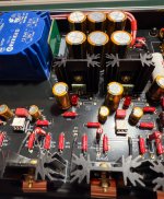
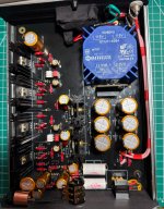
Another Whammy up and running ! I bought this used from eBay but desoldering a double sided board with ground planes wasn't worth the hassle, especially as the new boards are black and looking so good ! There were a number of things wrong with the board and the case, which I ought to have changed too - but that's a fresh build, so I had to keep something. So the enclosure is original and I'm not happy with it still, but everything inside in new.
I tested it with a 5532 and it was good but not exceptional - the plan was always to use the Muses 02. I put a 2134 in and it was definitely better, reinforcing what I'd heard with the Lehmann BCL, then the Muses 02 and it's certainly the best of the op amps I've tried so far, including the Burson V6 and V7. The bass is deep and strong, again much better than my Burson Soloist amplifier with the latest SP02 regulators and the V7 vivid op amps.
I've used an Evotronix Saligny universal rectifier rather than silicon diodes, just to try something new really. My scope isn't working right now so I can't measure the noise and I'm not sure I could go down that low anyway with my kit, it's just a shame it was appropriate to put it in with components facing the transformer due to the orientation of the pins, I'll consider swapping it round later.
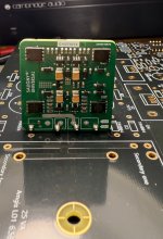
Regulators are Sparkos discrete regulators, I didn't feel like using 7815/7915 again, been using those for years so tried something new. Sparkos don't recommend adjusting the ground the device sees and Id' already fitted Audio Note capacitors when I read their application note that suggests a specific Panasonic 100uF cap, I'll change it later and see if makes much difference, they appear to be running perfectly currently. The heatsink is reaching about 45C, just slightly higher than the mosfets.
The pot is a TKD 601 stepped dual log pot, thought I'd try something different from the Alps, working perfectly. The knob is an Aliexpress special that arrived pre-scratched, such is life !
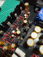
Power caps are Nichicon 4700uF, all the other electrolytics are Audio Note Kaisei, the main rail caps are 1000uF 25V, I've got some Charcroft silver mica caps to go in, Wima bypass with a couple more on the back of the board. The resisters are PRP PR9372 half watt which is why they're a tight fit, the 10 ohm are 1 watt, probably unnecessarily, except the power supply resisters where I reused some Takman metal film I had.
The input cable is BICC silver plated OFC copper, output cable is Duelund CC08, solid copper with a cotton and oil insulator... sometimes it's nice to try something new 🙂
Just listening to Anne Bisson, Do what you Please, and the double bass in the background is perfectly defined and deep with her voice quite forward and the percussion, cymbals, still clear and sharp. This amp is pretty good ! Kraftwerk earlier with Computer Love and Robots remixes was really enjoyable. Even Joni Mitchell CD, Blue, sounds enjoyable which it isn't always on cheaper kit.
The photos are from the first trial fit in the case, so I still need to clean the board a final time and adjust the length pf the input cables, I'm also really unhappy with the IEC mains connector, I covered the inside of the case with heatproof cloth tape to match the black PCB and ot some over the IEC connecter until I can decide what to do. I'm not sure about the copper coil cable holder either.
Whammy is good enough to clearly highlight the differences between the SMSL-SU1 DAC from eBay for £50 and my Chord Qutest, the difference is noticeable.
Many thanks to Wayne, Nelson, 6L6 and everybody on this forum for providing an incredible project, support and assistance and making it possible. What a great bunch of people ! 👍😎
Edited to add that I bought 20 each of the mosfets and matched them, there were some outliers which were well outside of the usual bell curve.
I tested it with a 5532 and it was good but not exceptional - the plan was always to use the Muses 02. I put a 2134 in and it was definitely better, reinforcing what I'd heard with the Lehmann BCL, then the Muses 02 and it's certainly the best of the op amps I've tried so far, including the Burson V6 and V7. The bass is deep and strong, again much better than my Burson Soloist amplifier with the latest SP02 regulators and the V7 vivid op amps.
I've used an Evotronix Saligny universal rectifier rather than silicon diodes, just to try something new really. My scope isn't working right now so I can't measure the noise and I'm not sure I could go down that low anyway with my kit, it's just a shame it was appropriate to put it in with components facing the transformer due to the orientation of the pins, I'll consider swapping it round later.
Regulators are Sparkos discrete regulators, I didn't feel like using 7815/7915 again, been using those for years so tried something new. Sparkos don't recommend adjusting the ground the device sees and Id' already fitted Audio Note capacitors when I read their application note that suggests a specific Panasonic 100uF cap, I'll change it later and see if makes much difference, they appear to be running perfectly currently. The heatsink is reaching about 45C, just slightly higher than the mosfets.
The pot is a TKD 601 stepped dual log pot, thought I'd try something different from the Alps, working perfectly. The knob is an Aliexpress special that arrived pre-scratched, such is life !
Power caps are Nichicon 4700uF, all the other electrolytics are Audio Note Kaisei, the main rail caps are 1000uF 25V, I've got some Charcroft silver mica caps to go in, Wima bypass with a couple more on the back of the board. The resisters are PRP PR9372 half watt which is why they're a tight fit, the 10 ohm are 1 watt, probably unnecessarily, except the power supply resisters where I reused some Takman metal film I had.
The input cable is BICC silver plated OFC copper, output cable is Duelund CC08, solid copper with a cotton and oil insulator... sometimes it's nice to try something new 🙂
Just listening to Anne Bisson, Do what you Please, and the double bass in the background is perfectly defined and deep with her voice quite forward and the percussion, cymbals, still clear and sharp. This amp is pretty good ! Kraftwerk earlier with Computer Love and Robots remixes was really enjoyable. Even Joni Mitchell CD, Blue, sounds enjoyable which it isn't always on cheaper kit.
The photos are from the first trial fit in the case, so I still need to clean the board a final time and adjust the length pf the input cables, I'm also really unhappy with the IEC mains connector, I covered the inside of the case with heatproof cloth tape to match the black PCB and ot some over the IEC connecter until I can decide what to do. I'm not sure about the copper coil cable holder either.
Whammy is good enough to clearly highlight the differences between the SMSL-SU1 DAC from eBay for £50 and my Chord Qutest, the difference is noticeable.
Many thanks to Wayne, Nelson, 6L6 and everybody on this forum for providing an incredible project, support and assistance and making it possible. What a great bunch of people ! 👍😎
Edited to add that I bought 20 each of the mosfets and matched them, there were some outliers which were well outside of the usual bell curve.
Attachments
Last edited:
I am very impressed with the neatness/clean of the build that you have done here. It is what I try to do but rarely do I get something that looks near this good. I especially like the front shot of the 'green circuit board'. Other wise it remains anonymous. The TKD pot is a favorite of mine due to its build quality. After all, it actually gets used mechanically speaking. I will go a step further and ask what solder do you like to use in builds. I have 4 different solders, all really good, but that just kind of happened in a trade.
Musical Fidelity did know how to make the looks in some of their equipment, but yah, the actual build was a bit short. I went through iterations of reclaiming the Can series and it was fun, but there was a lot to do, laughably with the 12 volt power connections which were all crap.
Oh and of course, you're going to sell this at an outrageously low price, right?
Last edited:
Thanks, I try to make it look good. I remember buying a used Sugden A25 amplifier a few years ago, it's from 1989, manufactured in Yorkshire, England by Sugden Audio, it was a budget model to sell along side their famous A21 class A amps, but inside it was better laid out and assembled than many more expensive amplifiers. Same for the old Audiolab amps of the 1980's and 1990's, before they were bought by IAG. It's also theraputic 🙂
The solder I use is just a midrange, quality solder with high purity tin and silver, this one: https://www.hificollective.co.uk/components/solder/ss-47-oyaide-silver-solder.html I need a new solder station as the current one is failing to detect when it needs to heat, so soldering onto ground planes is hit and miss.
Musical Fidelity missed a trick, they had Tim de Paravicini design a brilliant, musical, amplifier then they built it using spare bits they found down the back of the sofa.
Thanks for all the tips. I finally figured out the issue - it is the pots! I think the Alps "blue velvet" from Parts-Express inherently have imbalance issue at low volumes. I've tried 3 and all have the same issue. I got some cheap pots from eBay - knockoffs from China and they work much better!As a sanity check if you still have the old pot it would be worth measuring it out of circuit.
Turn it to minimum just as if it were in the amp and then turn it up a little by about the same amount of rotation you would be using when the the worst imbalance occurs. Now measure the resistance on each gang as follows.
From middle leg to one of the end legs. Note the result down.
From middle leg to other end leg. Note the result down.
From end to end. Note the result down.
Do the same for the other gang. So that is six readings. When you measure make sure your fingers are not touching the probes or pins at that will alter the result. Lets see what the imbalance is.
Make 100% sure these parts are correct in value (I think we did this but check). Differences in some of the resistor values (actual incorrect values, not tolerance) could interact with the pot and give an apparent gain difference. Unlikely but check.
Don't use a log pot 🙂 They are often terrible for channel balance. Use a linear pot and fake the log law with the addition of a single resistor if you wish which goes from wiper to ground.
-Max
- Home
- Amplifiers
- Pass Labs
- "WHAMMY" Pass DIY headphone amp guide