I said a long time ago, Chinese rotary switch with SMD resistors is death for that Alps. Both sonically and in terms of channel balance. 🤣
I put in a 100k pot because I had a few pieces at home. That's what I use for tube devices. For Whammy it is better to take a 20k or 50k pot.
I put in a 100k pot because I had a few pieces at home. That's what I use for tube devices. For Whammy it is better to take a 20k or 50k pot.
@Mooly , Do you have a recommendation on a particular linear pot? I believe linear pot provides larger range at the lower volumes and I would like to try this.As a sanity check if you still have the old pot it would be worth measuring it out of circuit.
Turn it to minimum just as if it were in the amp and then turn it up a little by about the same amount of rotation you would be using when the the worst imbalance occurs. Now measure the resistance on each gang as follows.
From middle leg to one of the end legs. Note the result down.
From middle leg to other end leg. Note the result down.
From end to end. Note the result down.
Do the same for the other gang. So that is six readings. When you measure make sure your fingers are not touching the probes or pins at that will alter the result. Lets see what the imbalance is.
Make 100% sure these parts are correct in value (I think we did this but check). Differences in some of the resistor values (actual incorrect values, not tolerance) could interact with the pot and give an apparent gain difference. Unlikely but check.
Don't use a log pot 🙂 They are often terrible for channel balance. Use a linear pot and fake the log law with the addition of a single resistor if you wish which goes from wiper to ground.
I also believe that the original Alps made in Japan should not have these issues.
-Max
Nothing to specific I'm afraid because I haven't bought any in a long time. I have found these OMEG pots to be surprisingly good though and inexpensive:
https://www.omeg.co.uk/potentiometers/unswitched/eco/eco-2-gang/

And of course ALPS.
Did I post this earlier, can't remember:
https://sound-au.com/pots.htm
Look at the headers for 'Potentiometer Tapers' and 'Changing the Law of a Pot'

https://www.omeg.co.uk/potentiometers/unswitched/eco/eco-2-gang/
And of course ALPS.
Did I post this earlier, can't remember:
https://sound-au.com/pots.htm
Look at the headers for 'Potentiometer Tapers' and 'Changing the Law of a Pot'
I have never liked those scares in DIY where what you just did is going involve extensive repair. The repair is fine if you know the problem. To get right to it, I bought one of the Burson V5i chips because I think this is a strong point of the versatility of the Whammy and I have heard a few that I enjoy. But no, I want to be careful and protect the chip, so I wired a bypass .1uf cap across what I thought was pin 1 and 8 (comically, I already had one that was made for me but couldn't find it). Does it really matter? Bad things happen if you mis wire that is what I know for sure. The good news is that the Burson survived, the power supply seems unaffected, and the only real casualties were the two opto couplers. That's not bad given the situation. The real PITA here is I have a problem with overbuilding, meaning to go back into my work is not a nice thing to have to do.
I must confess that the very hardest part is that feeling of stupidity and failure. It is temporary, but heavy for me to bear. All of this could have been avoided if only I checked my work. But folks it is who I am and no amount of pain seems to be enough. Make it through your projects so that you can feel a win again. Don't leave it as a dark reminder of a part of your self image that needs encouragement.
Fortunately there is this site which I follow closely to learn and with practice on new projects (I don't get it right the first or second time), something to actually be proud of arises.
BTW, the Burson sounds just fine.

Hey! I replaced the parts today and soldered everything in. I plugged it in and did a listen and there's no sound at all, even at high volume.7815 is dead.
Attachments
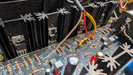
Rule 1 is always check voltages. Are you getting the expected voltage at the regulators, in and out? At the opamp? At the mosfets?
Good point, apologies. I did test the regulators. 7915 is -24.9v and 7815 -5.4v IN and OUT is -24.2 and -8.5(so I'm guessing something is wrong here.) The two FQP3P20 I replaced, the one closest to the back is -16.9v the second from the front is -13.4vRule 1 is always check voltages. Are you getting the expected voltage at the regulators, in and out? At the opamp? At the mosfets?
Just be sure, the 7915 and 7815 have different pinouts, are you checking the right pins? Both outs are on pin 3 but in on the 7915 is pin 2 and on the 7815 it's pin 1.
What are you seeing on pin 4 and pin 8 of the opamp?
What are you seeing on pin 4 and pin 8 of the opamp?
7915 -27.0v on pin 2 (middle pin right?) and 7815 is 2.5v on pin 1 (looking at it directly the pin that's furthest on the left?) 7815 keeps fluctuating. It's currently 1.6 or 1.7vJust be sure, the 7915 and 7815 have different pinouts, are you checking the right pins? Both outs are on pin 3 but in on the 7915 is pin 2 and on the 7815 it's pin 1.
For the op amp pin I got -21.0 on pin 4 and -0.9 on pin 8
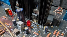
Okay, so you have to go further back. Check voltages on either side of the 5.1ohm resistors in the power supply, R 20, 21, 37 and 38. R 20 or 37 may have opened.
30.0v on R20, -27.5v on R21, -25.0v on R38, R37 keeps fluctuating and I can't get a solid reading. I should say some of them look burned out.Okay, so you have to go further back. Check voltages on either side of the 5.1ohm resistors in the power supply, R 20, 21, 37 and 38. R 20 or 37 may have opened.
EDIT: R37 is 4.0v
Attachments


hmm, it does look like things got a bit toasty in there. Makes sure your caps are discharged and then you can remove 37. Might be a good idea to replace R20 as well.
Ordering parts now. When I get a new 5.1ohm I should keep R37 removed correct?hmm, it does look like things got a bit toasty in there. Makes sure your caps are discharged and then you can remove 37. Might be a good idea to replace R20 as well.
Uh....will this still work? Lol (picture)Replace both R20 and R37. Take them out now and measure them. It would seem that R37 is open now and R20 probably got pretty hot before R37 popped.
Attachments

One says 5.2 ohm and the other is 5.0. also did the multi testerReplace both R20 and R37. Take them out now and measure them. It would seem that R37 is open now and R20 probably got pretty hot before R37 popped.
Attachments
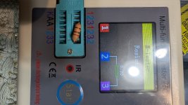
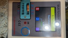
Something got hot there. Check the tracks under the board. You may have to repair tracks. You could put the resistors back in if you trust them but there seemed to be no current flow after R20. Possibly there was a bad solder joint??
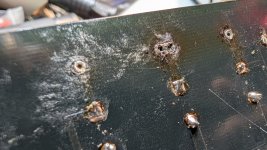
The pads at the junction of R20 and 37 don't look great but you can just hook the resistor leads together and solder them together. Check there is still a connection to C15.
There is, I measured 1.23v alsoThe pads at the junction of R20 and 37 don't look great but you can just hook the resistor leads together and solder them together. Check there is still a connection to C15.
- Home
- Amplifiers
- Pass Labs
- "WHAMMY" Pass DIY headphone amp guide