Thanks for the reply, I'll think about it. As for the 22uF caps, I'm just wondering if 16V is enough. I have some 22uF 16V bipolar left over from another project. If not, I will use these polarized 22uF 25V.

They do and they don't 🙂 The voltage on the caps can go nearly as high and as low as the rail voltage at full output but the other end of the cap also follows that voltage.
This is at full output into 32 ohms (and yes the opamp output really would look as distorted as this).
Green is the voltage on the centre point of the caps and red is the top of the upper cap and green the bottom of the lower cap. The voltage across each cap remains constant at all times. The gold trace is the amp output... now where did all that horrible distortion on the caps go 😉
That opamp is trying really hard. 😁
Muses bipolar will go then, but I don't think the sound will be worse than with polarized caps.
Muses bipolar will go then, but I don't think the sound will be worse than with polarized caps.
It is, but at lower levels things improve. It also depends greatly on bias current vs load impedance. Same as before but now -/+1 volt into the load. You can clearly see the constant voltage across the caps at around 4 volts.That opamp is trying really hard.
That already looks nicer. I didn't immediately realize that those 22uF are floating at the output of the opamp.
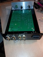
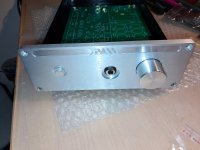
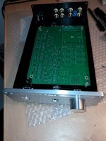
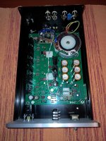
My intention is to use it primarily as a Line preamp, but to have the ability to run headphones when I want to. The advantage is that it can drive the amplifier with any input resistance. I reduce the gain, because 6x is too much for a Line stage with digital sound sources. I envisioned two Line inputs and two Line outputs (one for active SUB if needed). Practically the same as the one I did for @mikorist.
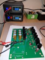
I just started, there will be a lot of work. First the mechanics, then the electronics.
My intention is to use it primarily as a Line preamp, but to have the ability to run headphones when I want to. The advantage is that it can drive the amplifier with any input resistance. I reduce the gain, because 6x is too much for a Line stage with digital sound sources. I envisioned two Line inputs and two Line outputs (one for active SUB if needed). Practically the same as the one I did for @mikorist.
I just started, there will be a lot of work. First the mechanics, then the electronics.
Attachments
Last edited:
Thank you. It looks nice, it will sound nice, the original output mosfets will arrive soon, everything else is of good quality (Nichicon, Dale, wires, etc.) No savings, this is my copy. 😊
I'm making slow progress with this, the problem is an excess of obligations and a chronic lack of time. What I would like to ask is about connecting the signal cables. I see many people use two wires in a shielded cable, one for the left channel and one for the right channel. Is it good because of channel crosstalk? When I made earlier Whammy and various other devices, each channel was in a separate screen, I think it's more correct.👍 that's looking really good 🙂
Attachments
That particular design, unfortunately, requires fairly long and multiple internal hookup wire lengths... have a look at Pass Labs and even First Watt designs... the input signal is routed straight away to the input board, where it gets terminated, so the hookup wiring length is like 30-40mm max. Some designs do not have any hook-up wiring; the RCA / XLR connectors are PCB mounted on the pre-amp PCB.
With the above in mind, I suggest that you try loose hook-up wiring (NOT the shielded mono microphone cables) first - one loosely twisted pair for one channel and the other loosely twisted pair for the other. If you can't hear the buzz - all good, do not use a shielded microphone cable at all. Just make sure the ground uniformity between the input ground, all chassis panels, and the volume pot case are at the same potential.
With the above in mind, I suggest that you try loose hook-up wiring (NOT the shielded mono microphone cables) first - one loosely twisted pair for one channel and the other loosely twisted pair for the other. If you can't hear the buzz - all good, do not use a shielded microphone cable at all. Just make sure the ground uniformity between the input ground, all chassis panels, and the volume pot case are at the same potential.
The first copy was absolutely noiseless, but I used shielded cables for the input and output signal, and separately by channel.
Thanks Wayne !
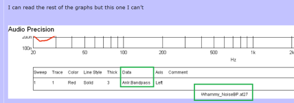
I can read the rest of the graphs but this one I can’t

Pardon my ignorance but I’m more used to reading something like say like this

I can read the rest of the graphs but this one I can’t
Pardon my ignorance but I’m more used to reading something like say like this
Ok I’m definitely not smart enough to decipher.
I thought it was done with a 1khz since wave.
Sorry fellas.
I thought it was done with a 1khz since wave.
Sorry fellas.
I thought it was done with a 1khz since wave.
An FFT of distortion spectra is usually done with a 1K fundamental tone, yes.
That graph isn't an FFT. It's noise over the audible frequency range, in example, looking at this graph you can see that the biggest lump is 4uV (4/1000000, four one-millionths of one volt) noise at 60Hz.
That's not a whole lot.
- Home
- Amplifiers
- Pass Labs
- "WHAMMY" Pass DIY headphone amp guide