This is like soccer: if you keep passing and passing, you can always overdo it and miss the goal.🤣My version has to be better. 😁

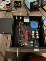
Hi all, I'm new here. The Whammy is my first "real" build of an audio component. I've got it completely assembled and it sounds amazing, with 1 caveat. I get a buzzing noise (sounds like ground loop) whenever I touch the chassis or volume knob.
I've measured the voltage on the ground it's always 0, or very nearly. I've moved my wires around, but no change in the buzz. The buzz increases and decreases with volume and completely disappears when I stop touching it.
I've been looking through this thread, but 268 pages is a lot of conversation to digest.
Anyone have any thoughts of what I can check next?
Pic included, in case I've made an obvious (to someone else) error.
Attachments
Last edited:

Probably the pot housing is not grounded. Either there is no good contact with the front plate or the front plate itself is not grounded.
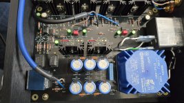
Hello all. I'm attempting to troubleshoot an issue with a Whammy my father recently built. Everything seems great, except there is a significant, consistent channel imbalance with the left channel much lower than the right. I tried quicky swapping the opamp and can rule that out. Any suggestions on where to start my troubleshooting?
In case something is obvious, here's a shot of the top. I haven't taken the board out yet, so don't have a shot of the bottom.

In case something is obvious, here's a shot of the top. I haven't taken the board out yet, so don't have a shot of the bottom.
Attachments
If you have access to an oscilloscope then finding this should be straightforward, if not then you will have to improvise.
The gain of the Whammy is determined by the values of the feedback resistors R4 and R1 and there corresponding opposite numbers in the other channel. You need to be sure these are correct and also that R2 and R3 are the correct values (and in the other channel).
Also make sure R39 and R40 are correct and the same between channels.
Beyond that you could try quickly linking the wiper of the volume control between channels. So one link tagged between the middle pins of the volume pot. That forces the same signal to both channels.
Imbalance still there? Yes or no?
R39 and R40 are both 2201F.
R4 and R8 are both 4751F
R1 and R12 are both 1001F
Guess I'll try the pot, though let me know if you have any other suggestions.
Thanks!
R4 and R8 are both 4751F
R1 and R12 are both 1001F
Guess I'll try the pot, though let me know if you have any other suggestions.
Thanks!
Thank you for the link! Given that my potentiometer is securely bolted to the face plate and that the entire case is metal and touching, I'm now suspecting the anodized treatment. Thanks to everyone that responded. Off to try this...
Just use a piece of wire to touch circuit board ground and to also touch potentiometer body. If buzz changes: Eureka! Now you can disassemble and sand off the paint / anodizing / powder coating. A nice long crocodile clipped insulated wire is great for this. You can clip one end to a component lead at board ground, and go poking around various places with the other end.
@jlconnor , these problems are common with anodized or plasticized aluminum. Aluminum oxide is an insulator, and it is very hard (the second hardest material after diamond). If tightening the screws alone is not enough to establish panel contact, I put star or elastic washers between panels which break through the oxide or plastic layer and connect the panels electrically.
I don't know how exactly the grounding was done in this case? The chassis should be connected to the safety GND, and the PCB GND connected to the chassis via a small capacitor (100-150nF) or a GND breaker circuit.
I don't know how exactly the grounding was done in this case? The chassis should be connected to the safety GND, and the PCB GND connected to the chassis via a small capacitor (100-150nF) or a GND breaker circuit.
Last edited:
R39 and R40 are both 2201F.
R4 and R8 are both 4751F
R1 and R12 are both 1001F
Guess I'll try the pot, though let me know if you have any other suggestions.
Thanks!
I haven't tested the pot yet, but wanted to post a picture of the bottom of the board. Again, in case anything obvious stands out. Let me know!
I've got a 0.33uF capacitor between the input shields and chassis ground that came with the kit.I don't know how exactly the grounding was done in this case? The chassis should be connected to the safety GND, and the PCB GND connected to the chassis via a small capacitor (100-150nF) or a GND breaker circuit.
@jlconnor As others have mentioned, the black anodization on the aluminum is a pretty good insulator. You need to scrape it off to bare metal near the interfaces and make sure there is raw metal touching raw metal between all 6 panels, and also where the potentiometer mounts. Look at steps #31 and 32 of the Pearl 3 guide for clear photos. https://guides.diyaudio.com/Guide/Pearl+3/28?lang=en
@NIXIE62 @Mark Johnson Thank you both! I took your advice and touched a length of wire from the pot housing to the ground and the buzz was instantly gone. I disassembled the chassis and used my trusty Dremel tool to rough it where each plate contacts the other and the hole for the chassis ground.
Sounds amazing! Thank you to everyone that responded. I'm really liking the audio DIY community and this forum.
Sounds amazing! Thank you to everyone that responded. I'm really liking the audio DIY community and this forum.
If it's not difficult for you, I have a few questions:The gain of the Whammy is determined by the values of the feedback resistors R4 and R1 and there corresponding opposite numbers in the other channel. You need to be sure these are correct and also that R2 and R3 are the correct values (and in the other channel).
1. I want to reduce the gain, is it better to put R4/8-4k75 and R1/12-2k2 or R4/8-2k2 and R1/12-1k?
2. Can I use Nichicon MUSE 22uF 16V bipolar capacitors instead of C12/17/22/25-22uF 25V? Does this generally have any effect on the sound or not?
The supply voltage will be +-15V.
Providing the opamp actually used is OK running at lower gain then either combination can be used. Either set of values are so low that any difference in noise is negligible. From a purely subjective point of view there are some that feel that running at higher gain can be beneficial. Only you can decide that one. Adding a resistor between the opamp inputs can be used to fool the opamp into thinking its running higher gain when it actually is not.
Like this. The overall gain is still set using the feedback resistors, the extra resistor increases the 'noise gain'. You might think it sounds better like this... or not 🙂 Only you can decide that one.

Keeping R4/8 at 4k75 reduces overall loading but again its a negligible difference.
Also don't discount just increasing R39/40 as an alternative. Sonically it could be a good option.
The caps are very tightly wrapped up within the overall feedback loop and my opinion is changing them won't achieve anything... but don't let that stop you trying them. I'm not a great believer in cap differences in good quality parts correctly used.
Like this. The overall gain is still set using the feedback resistors, the extra resistor increases the 'noise gain'. You might think it sounds better like this... or not 🙂 Only you can decide that one.
Keeping R4/8 at 4k75 reduces overall loading but again its a negligible difference.
Also don't discount just increasing R39/40 as an alternative. Sonically it could be a good option.
The caps are very tightly wrapped up within the overall feedback loop and my opinion is changing them won't achieve anything... but don't let that stop you trying them. I'm not a great believer in cap differences in good quality parts correctly used.
- Home
- Amplifiers
- Pass Labs
- "WHAMMY" Pass DIY headphone amp guide