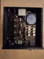
NOTHING TO SEE HERE! Just another completed Whammy! Assembly has been the most fun I've had in awhile. It fired up beautifully, as soon as I inserted an op-amp (LM 833); couldn't figure out why all I got was silence!
After twenty minute or so burn in, the sound absolutely blows me away, even using my old Ultrasone headphones from my desk at work.
I just switched to a Kimber PK-10 Power Kable and am listening to some Hi-Res files on one of my (Tidal-created) playlists.
Thanks to all that made this design and kit available.
JB

Question for the EE majors on the board, I'm considering adding balance pre-outs to my WHAMMY as I want to use it as a headphone amp and pre-amplifier for my speaker amp that is about 25 feet away from my desk. Considering something like this (Assembled DRV134PA Dual-channel Single-ended to Balance Board DC ±12V). Is there a place on the board I can tap to power it? And, do I need to anything to make sure I'm feeding the new board the right voltage? Thanks in advance.
DRV134PA max Vcc/Vee is + and - 18V... so as long as you don't go above that... the points to tap the voltages from, are straight after the voltage regulator IC's. Also, position the new single-end to balanced board in such a way so that the signal feed wire length from WAHMMY to AIDIO IN is minimal.
Thanks Extreme_Boky.DRV134PA max Vcc/Vee is + and - 18V... so as long as you don't go above that... the points to tap the voltages from, are straight after the voltage regulator IC's. Also, position the new single-end to balanced board in such a way so that the signal feed wire length from WAHMMY to AIDIO IN is minimal.
Another potentially dumb question I've read on the thread where some have used R10 and R14 for 12v LED power switches with a 4.7K limiting resistor. The DRV134PA is listed at 10k ohms. Do I need to measure the impedance of R10/R14 and then get the appropriate limiting resistor if necessary
You'll need to wire the new PCB for voltage input (+ and - 15-18V DC) AND for the audio signal input.
Voltage input:
connect the VOUT (pin 3) of each voltage regulator to DC input on the PCB. The ground feed should come from that middle point where all 4 3300uF capacitors (C19, C18, C15 and C14) are connected.
Audio analog signal input:
connect the middle points of R16 & R22, and R29 & R32 via 100-ohm resistors (one for each stereo channel), to PCB analog inputs. The resistor value is not critical at all; anything between 100 - 500 ohms or so.... will do just fine.
You do realise that, with the additional PCB, you will have 5-6 capacitors in the audio signa path:
C5, C26, C17&C12.... plus an additional 2 on the new PCB. Too much for you? If yes, consider different options... maybe..?
C5, C26, C17&C12.... plus an additional 2 on the new PCB. Too much for you? If yes, consider different options... maybe..?
Not to mention three IC op-amps (on a single chip!) per channel, whose sound quality is doubtful.Question for the EE majors on the board, I'm considering adding balance pre-outs to my WHAMMY as I want to use it as a headphone amp and pre-amplifier for my speaker amp that is about 25 feet away from my desk. Considering something like this (Assembled DRV134PA Dual-channel Single-ended to Balance Board DC ±12V).
You do realise that, with the additional PCB, you will have 5-6 capacitors in the audio signa path:
C5, C26, C17&C12.... plus an additional 2 on the new PCB. Too much for you? If yes, consider different options... maybe..?
When I asked about this kind of thing in a different connection, I was referred to this document. It should have its own sticky thread. In fact, I've just posted a separate thread with that suggestion and said there everything I was about to say here. It's here:
https://www.diyaudio.com/community/threads/balanced-outputs.387060/
now. Suffice it to say here that there are a lot of really simple, and in some cases very cheap, options.
I always pinch myself to force the brain to switch to reality: this is a DIY amplifier... the joy and satisfaction should come from the fact that one can start from a bunch of parts... and arrive at a fully functional amplifier.
The OP AMPs can be rolled.... the power supply rails can be improved.... the sound coupling caps can be removed (with a correct choice of OP-AMP and a bit of tweaking)... that's a lot of fun in my book.
What you can't get is... a fully balanced signal path.
The full kit would cost AU$500 or so to land in Australia. However, it does look very professional - nice indeed.
I need a fully balanced signal path for my needs. I parted away from sound coupling caps and ICs more than a decade ago. So, yes, there are other options. But then, look at that second paragraph... all that fun... building something out of thin air... tweaking, adjusting.... all that -> gone!
Edit:
....AND a very important element that we usually completely overlook... there's a team/dedication behind putting that full kit together!!! That in itself deserves the highest of accolades and congrats. So hard, tiring and demanding -> and so easily overlooked and underappreciated.
Last edited:
I know what kinds of reasons there might be. I'm curious why you specifically need it. I also ask because Wayne, for example, insists that is NOT needed in the phono stages, and that adding all that circuitry would be counter-productive. And that's with signals as tiny as they come.
I'm a big fan of balanced operation, don't get me wrong. I run 40ft cables preamp to amp, so balanced is the only way to go.
I'm a big fan of balanced operation, don't get me wrong. I run 40ft cables preamp to amp, so balanced is the only way to go.
With WHAMMY, something like this would be my prefered solution to get balanced-out:When I asked about this kind of thing in a different connection, I was referred to this document.
Last edited:
I know what kinds of reasons there might be. I'm curious why you specifically need it. I also ask because Wayne, for example, insists that is NOT needed in the phono stages, and that adding all that circuitry would be counter-productive. And that's with signals as tiny as they come.
I'm a big fan of balanced operation, don't get me wrong. I run 40ft cables preamp to amp, so balanced is the only way to go.
Did you ask Wayne to show you an example of a balanced-out phono cartridge???
Another Whammy live and kicking! Thank you to all involved in designing and supplying this wonderful kit. It’s my first kit and I’ve really enjoyed building it. AND, best of all, it worked first time. It is replacing a capricious point-to-point B1 driving my SIT-2 and I am delighted!
Did I say how pleased I am?😀
Did I say how pleased I am?😀
As evidenced by my post above, I just finished mine too. Currently trying a Sonic Imagery Enh994 TichaAnother Whammy live and kicking! Thank you to all involved in designing and supplying this wonderful kit. It’s my first kit and I’ve really enjoyed building it. AND, best of all, it worked first time. It is replacing a capricious point-to-point B1 driving my SIT-2 and I am delighted!
Did I say how pleased I am?😀
I know what kinds of reasons there might be. I'm curious why you specifically need it. I also ask because Wayne, for example, insists that is NOT needed in the phono stages, and that adding all that circuitry would be counter-productive. And that's with signals as tiny as they come.
I'm a big fan of balanced operation, don't get me wrong. I run 40ft cables preamp to amp, so balanced is the only way to go.
Not to get too OT, but,
A good solution for the output of a phonostage is a balanced line driver, like the THAT1646 or DRV134 series. Would give the ability to have the phonostage very close to the turntable if you like/needed. Of course if you don’t have a balanced preamp you could just leave that unstuffed. (This may be a little foreshadowing on my part…)
Congrats 🙂As evidenced by my post above, I just finished mine too. Currently trying a Sonic Imagery Enh994 Ticha View attachment 1065172op-amp and the sound is amazing.
I wanted to try those but they seemed out of stock then.
Where did you order them?
How do they perform compared to the other Op Amps you've tried?
I've been using the Sonic Imagery Labs dual discrete for most of the year and they are excellent. I have no desire to try any other op amps in my Whammy now but it would be nice to have a Whammy board layout that would allow using single channel discrete Op Amps in the standard API footprint because I have lots of different flavors of them used with pro audio gear that I would love to try in the Whammy.
Sonic Imagery Labs sells direct and if I remember right they offer these with a parts upgrade that gets you tantalum chip resistors and maybe something else. It's not obvious on the web site when ordering so if that interests you hunt around for it. I may have chosen that but I didn't notice it until after I'd ordered and they don't make mention of the upgrade price.
If you like high quality parts for the Whammy try out Belleson SPX voltage regulators. I've been using the 24 Volt version with the Sonic Imagery Labs dual discrete so I have lots of headroom to drive most anything as a preamp. Belleson has an real interesting web site which shows direct comparisons with all kinds of other voltage regulators including the Jung Super regulator, Shunt types and many others. It is impressive. He sells direct but you may find a better price at Parts Connexion if they are in stock.
I couldn't be happier with my Whammy. I used the Quasimoto style snubbers on the power transformer. I squeezed in four film capacitors to jumper the 22 uF electrolytics downstream of the op amps and I put in a pair of two pin headers that let me jumper across the input film capacitor pair since most of my sources have no DC so they aren't needed but capacitors are there if I do need them.
It's been fun but the best part is enjoying the music. The hardest part was getting the film caps to fit with the electrolytics.
This Whammy deserves it's picture posted after describing it above. Holes in the circuit board were drilled to fit the two film caps as part of the snubber networks. The other two R/C series snubber parts were soldered to the bottom of the circuit board. Holes were drilled to fit the input capacitor bypass jumper headers seen between the caps and the Alps dual pot. Holes were also drilled to get the film capacitors to fit near the four electrolytic caps. All of the signal cable connections are taken from the bottom of the circuit board. Also on the bottom of the board are small film capacitors across the large electrolytic caps.
Attachments
- Home
- Amplifiers
- Pass Labs
- "WHAMMY" Pass DIY headphone amp guide