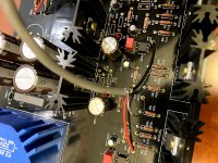
I also added .1uF/200V KEMET XR7 multilayer ceramic caps from opamp pins 4 and 8 to ground for additional bypassing.
Thanks again!
Are any of the heatsinks getting warm ?
No, although I am not keeping it on for any length of time.
Input voltages at op amp socket - pins 4 and 8 wrt ground?
pin 4 -16.64V
pin 8 +16.63V
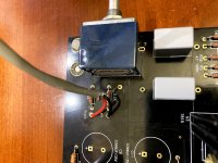
Input and output wires: I don't think I've seen the shield used for ground.
Noted, didn't have anything better to use for testing purposes, had this Belden cable lying around.
Check voltage drop across the source resistors to start with.
Not sure which ones are called "source" resistors.
The voltage drop on R1, R2, R12, R7, R39, and R40 is zero.
Can you post your photos here please? The link you sent requires joining google photos or something, which I don't have time or the desire to do.
Sorry about that. I am a new member. Doesn't look like I can post images on here. I looked at FAQ, I don't have "Quick Links > Networking > Pictures and Albums" menu. Am I doing something wrong?
Also, are you using the DIYStore Whammy board or your own? You did not state that above.
I am using the DIYStore's Whammy board (black PCB)
RE: the MOSFETs, have you tested them with a tester or using this technique?
No, I haven't. I might havet to take them out one-by-one to test.
Sorry about that. I am a new member. Doesn't look like I can post images on here. I looked at FAQ, I don't have "Quick Links > Networking > Pictures and Albums" menu. Am I doing something wrong?
When you're posting (don't use "quick reply") there is a paper clip icon above the text box. Use that to attach images.
Can you post your photos here please? The link you sent requires joining google photos or something, which I don't have time or the desire to do.
Ok, thanks to A Jedi, I figured out how to upload attachments!
In fact, after fiddling around it seems that:
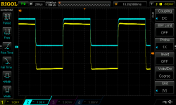
(1) both channels are responsive - I can connect the square wave from a scope to either channel and see the corresponding output channels get amplified. In both screenshots the cyan line (Ch2) is for the input while yellow line (Ch1) is for the output.
(2) the right channel seems to be DC-offset by some random value, -0.56V currently. One can see this DC offset in one of the scope screenshots that I attach to this message
(3) the MOSFETs for the right channel are both noticeably warmer than the left ones
Attachments

Perhaps check offsets without the opamp, no inputs or output, volume minimum.
This is from Wayne, same as credited on the board. Jim/6L6 is the other.
"WHAMMY" Pass DIY headphone amp guide
Welcome to diya. I used Google and site search to find the post above. The direct thread search here doesn't work for me.
site:diyaudio.com whammy offset - Google Search
This is from Wayne, same as credited on the board. Jim/6L6 is the other.
"WHAMMY" Pass DIY headphone amp guide
Welcome to diya. I used Google and site search to find the post above. The direct thread search here doesn't work for me.
site:diyaudio.com whammy offset - Google Search
Last edited:
Looks like the issue got resolved!
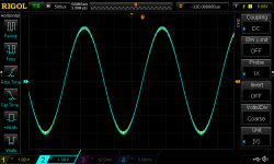
Turns out the problem was with excessive use of paste flux (LACO Flux-Rite 90 to be precise). I thorougly washed both sides of the board with isopropanol, cleaned it with kimwipes, and blew off with compressed air, repeated a few times, and now it works as it should!
Attached is the 440Hz sine wave, Ch1 is "right out", Ch2 is "left out" (generated with a Khadas Tone Board and Online Tone Generator). The offset is negligible, the gain for left and right is almost identical.
That was easy... Thanks for the help!
Attachments

Should I bother grounding the mu-metal or not necessary?
No. You don't ground magnetic shielding.
It works due to magnetic permeability.
step 27 (example of what NOT to do)
Hiya!
I was looking for examples/illustrations of grounding schemes and got into the again wonderful build-guide by 6L6.
Step 27 strikes me: Why shouldn't the IEC be placed in a distance to the tranny?
Hiya!
I was looking for examples/illustrations of grounding schemes and got into the again wonderful build-guide by 6L6.
Step 27 strikes me: Why shouldn't the IEC be placed in a distance to the tranny?
Why shouldn't the IEC be placed in a distance to the tranny?
To keep the power wires as short as possible and therefore reduce any potential noise getting into the delicate signal.
To keep the power wires as short as possible and therefore reduce any potential noise getting into the delicate signal.
That’s what’s puzzling me.
6L6 writes
»Second image: Use this photo as an example of what NOT to do -- please move the IEC inlet to the middle of the back panel to get it away from the transformer.«
The image: https://d17kynu4zpq5hy.cloudfront.net/igi/diyaudio/ujhc1qvXZY2bkhua.large
So, it is to conclude that... the iec should be further away? (Probably just because the space was getting a bit too narrow, but it could have other reasons...)
I think 6L6 was implying that, it was a bloody pain in the ars3 having the IEC connector so tightly fitted against everything. Having some space might make things easier to connect up.
If the case was a little bigger with more clearance then I am sure he wouldn't complain about the situation.
If the case was a little bigger with more clearance then I am sure he wouldn't complain about the situation.
Last edited:
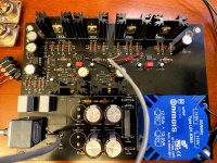
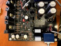
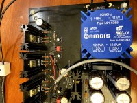
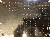
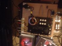
Finally got round to building the Wammy so I could roll opamps, last time I played with them was when the OP27 & OP37 where released.
Built with +-15V supplies, no C2 & C7, links in place of C26 & C27, 2SK2013 & 2SJ313 output, nailed it on a lump of plywood, using it as a pre.
Tried Muses01, not impressed, too HiFi, also veiled, a bit like listening through a blanket.
I have the Muses02, but I don't think I'll bother to audition.
Banged a couple of Muses03 on a brown dog, these are a different kettle of fish, the sound is acceptable, almost as good as a high quality discreet pre, no real complaints.
Need to get my hands on some Burson's.
Sorry about the quality of the photos, my phone is not well.
Attachments

Last edited:
I've got a couple of spare single channel pcbs here that I can send over if you like - Prasi develop a simple single channel version - no included power supplies as intended for shunt regs. Can make your own provision for V6 ICs, etc ...
I got the boards Friday. I will start populating them.
Thanks for that.
That should keep me from going insane for a while.
Hahahahahaha

- Home
- Amplifiers
- Pass Labs
- "WHAMMY" Pass DIY headphone amp guide