I've used this $9.00 19mm diameter Chinese switch successfully:
https://amazon.com/gp/product/B07931ZKC1/ref=ppx_yo_dt_b_search_asin_title?ie=UTF8&psc=1
It has a 250VAC/5A main contacts rating. Just add additional external resistance to the LED portion as needed.
Name brand manufacturers (E-Switch, TE, etc.) start at around $14.00. The original Bulgin switches, the ones everyone copied, are about $22.00 and up.
You could always add a relay for the mains and still be well under the Bulgin price.
Oh - and the Whammy PS is incredibly well behaved, no need for a soft start.
Last edited:
Yes its nice switch 19mm ( i use them with LED and versions without LED) - its possible to get it cheaper without socket imho.
Attachments

Last edited:
Yes its nice switch 19mm ( i use them with LED and versions without LED) - its possible to get it cheaper without socket imho.
Nice builds. Are your Leach amps the Marshall Leach Low TIM amplifier? I built several back in the mid-1970s and they pretty much outperformed everything at the time.
I don't want to hijack the topic.. but yes - true classic low tim 4.5 ....
but Whammy is very good too ( my younger son uses it and has already learned to solder himself)..
but Whammy is very good too ( my younger son uses it and has already learned to solder himself)..
Attachments


Okay guys, as promised here is a review of the rest of the OP Amps I bought to test in the whammy. These ones are all on 8P-DIP adapters:
Again I used my HiFiMan HE400i headphones and Topping D50 DAC. I used FLAC audio 96Khz 24 bit. Evanescence Synthesis album.
8P-DIP Adapter based OP Amps:
OPA1622 SoundPlus:
Operating Voltage: 18v MAX
Slew Rate: 10v/µs
DC Offset: L -152.6mV / R -154.2mV
FET: No
Package: VSON-8
Notes: This is an excellent OP Amp, High clarity, wide sound stage, no noticable distortion, this one is truly stunning from the mids and trebles right through to the vocals. DC offset is extremely high in this one. Maybe due to the extra onboard components of the DIP adapter. There are some resistors and capacitors.
OPA1662 SoundPlus:
Operating Voltage: 36v MAX
Slew Rate: 17v/µs
DC Offset: L 76.2mV / R 74.8mV
FET: No
Package: SOIC-8
Notes: Very wide sound stage, clear with good mids and trebles, vocals prominent and up front. Overall nice sounding OP Amp. DC offset is also quite high.
OPA2189:
Operating Voltage: 36v MAX
Slew Rate: 20v/µs
DC Offset: L -0.1mV / R -0.2mV
FET: No
Package: VSSOP-8
Notes: This is quite a nice OP Amp with clear vocals, wide soundstage and balanced mids and trebles. Very low DC offset.
OPA1692 SoundPlus:
Operating Voltage: 36v MAX
Slew Rate: 23v/µs
DC Offset: L -34.8mV / R -34.9mV
FET: No
Package: SOIC-8
Notes: Crystal clear, good sound stage and up front vocals. Sounds really nice this one.
OPA2210:
Operating Voltage: 18v MAX
Slew Rate: 6.4v/µs
DC Offset: L -0.1mV / R -0.2mV
FET: No
Package: SOIC-8
Notes: This OP Amp sounds incredible. Very wide soundstage, clear mids and treble with vocals just at the right distance. This one really brings out the finer details. Very low DC offset. Really like this one.
Okay guys I am hoping someone can shed some light, as you can see in previous posts with the amount of OP Amps I have tested I have had some mainly the ones on DIP adapters that have had quite a high DC offset. Would it be possible to replace the R3 and R5 resistors for trimpots to zero any negative or positive offset or is there another way or am I completely looking at this wrong?
Should I have a ground cap for both input and output RCA to ground or just one for all of them.
Should I have a ground cap for both input and output RCA to ground or just one for all of them.View attachment 775967
I have a global ground for the input and output connected to a cap so it should be fine.
Sorry Brian for my tardy reply to your …
Sounds interesting. Since the Loki uses an external 16VAC transformer and an internal regulated LM317/LM337 bipolar supply, how did you implement a linear supply? Did you hack the PCB?
I just replaced the external supply with an AMB Sigma 22 and spot soldered to the output of the LM reg chips - not exactly the best engineering, I know - I wasn't expecting much change as it's a really well thought out little design (not simple at all, actually) but I was hoping to add a little more 'body' and get rid of that slightly 'thin' sound but this is about the limits of my electronics competency.
I did look at playing with that 1662 chip but decided to leave things well alone (quite limited electronics competency) as the device isn't intended to be a resurrected 'Cello' - it'll be interested to see what you make of it, particularly with the ';Whammy' amp.
My 'Whammy' uses a set of quite compact thru hole component diy boards, uses the Burson V6 classic on input, and it runs at about 120mA on the output transistors via the AMB Sigma 22 power supply driving the HE 500 headphones (with ViaBlue mike cable for leads) - analogue signal is via the Ayre QB-9 dac - you can see I'm a bit of a 'fiddler'!
Yeah just had a friend offline say the same. He said I should star ground them all in the middle of them with a 1nf 100v kemet ceramic cap each. Just tested it and sounds pretty damn good. Can't hear any hum till I turn the amp to unlistenable levels. But that's not the point will surely improve with like you said. Will let you know how it goes! ThanksHello HatlessChimp,
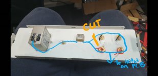
I would cut the loop around your RCAs (possible ground loop). Will not necessarily be bad as you did.
I marked the pic where I would cut / break.
Greets
Dirk


My experience with hum or groundloops - try and error. 😀
I often test it with a few cables and crocodile clamps what is the best
grounding. Star grounding is - most often - a good solution.
Enjoy your WHAMMY!
I have built two WHAMMYs. I like them a lot!!!
Greets
Dirk
I often test it with a few cables and crocodile clamps what is the best
grounding. Star grounding is - most often - a good solution.
Enjoy your WHAMMY!
I have built two WHAMMYs. I like them a lot!!!
Greets
Dirk
I often use these switches - I've never had a problem. But someone told me about an internal short circuit when mains burns PSU through led wires...
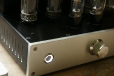
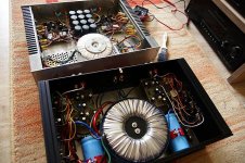
Good layout.
Clear separation of power circuit and small signal circuit.
Including placement of pot, output socket and power switch.
Examplary. 👍
Patrick
.
Attachments

Hello labjr,
I tried different voltages on my WHAMMY-prototyp before the official pcb
came out. I have built a regulated PSU very similar to Waynes design.
I used the 'oldtimers' LM317 / LM337 to make the voltage adjustable. You can
see the blue trimmers on the photo.
My opinion is: it was very difficult for me to hear a difference in the sound
depending on the rail voltage. I tried between +-15 to +- 17.8 volts (depending on the opamp). But i am pretty sure you can measure a difference.
But I could hear a big difference in using different opamps at the inputstage.
Every opamp had its own 'character'.
And I am a friend of high rail voltages.
But that is my experience. Yours can be different.
My opinion is: build the WHAMMY and try it. You will like it.
And try different opamps....
Greetings from Dirk
Hi is there any chance you could help me with the adjustable PSU please? Do you have a gerber or schematic you are willing to share please? I am looking to do the same based on CRCRC but with adjustable voltage output via trimpots.
Regards
I got the Burson V6 Vivid op amp for my WHAMMY. It's expensive, but it's also clearly better than any of the others I've tried. The others seem to add their own subtle character, but the V6 is more like lifting the veil to a very clear, balanced and musical sound. I liked it right away but apparently it's a little hard sounding when brand new, and gets more relaxed and liquid sounding over time. Is it worth spending $70 vs $10 for some of the nicer standard op amps? That's a personal call I guess, but I'm happy I bought it.
I've built the WHAMMY and the NuHybrid recently. What other current DIY headphone amp projects would people recommend?
I've built the WHAMMY and the NuHybrid recently. What other current DIY headphone amp projects would people recommend?
I've built the WHAMMY and the NuHybrid recently. What other current DIY headphone amp projects would people recommend?
I recommend the T2, although it has lower gain than either the WHAMMY or the NuHybrid. You can see if Mark Johnson is willing to sell you a board or wait until it hits the diyAudio store. Here's the link to the T2 forum:
Single ended class-A headphone amp using two transistors: T2
Also, you may want to consider correcting the output polarity of the NuHybrid. The tube inverts the signal an its way through and I, for one, can hear the difference. I corrected my NuHybrid by using Jensen input transformers with the primary leads reversed. Keep in mind you will need to add the damping network shown in the Jensen data sheet if your input pot is larger than 10K ohms. Another worthwhile mod is to set up the NuTube biasing similar to the B1Korg. This is done by changing the plate resistors to 332K and setting the plate voltage at 9.75VDC.
Jensen JT-11P-1 Line Input Transformer
- Home
- Amplifiers
- Pass Labs
- "WHAMMY" Pass DIY headphone amp guide