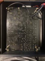
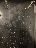
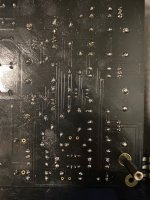
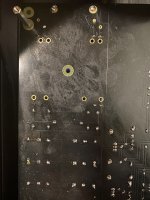
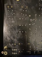
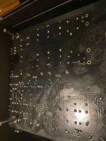
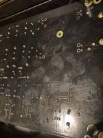
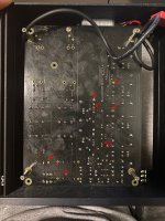
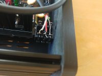
Here are the solder situation of the back.
Attachments
-
 WhatsApp Image 2022-04-03 at 22.58.23.jpeg513.4 KB · Views: 178
 -
 WhatsApp Image 2022-04-03 at 22.58.24 (1).jpeg502.2 KB · Views: 174
 -
 WhatsApp Image 2022-04-03 at 22.58.24.jpeg471.6 KB · Views: 142
 -
 WhatsApp Image 2022-04-03 at 22.58.25.jpeg481.8 KB · Views: 147
 -
 WhatsApp Image 2022-04-03 at 22.58.26 (1).jpeg472 KB · Views: 124
 -
 WhatsApp Image 2022-04-03 at 22.58.26.jpeg494.9 KB · Views: 147
 -
 WhatsApp Image 2022-04-03 at 22.58.27 (1).jpeg564 KB · Views: 131
 -
 WhatsApp Image 2022-04-03 at 22.58.27.jpeg531.3 KB · Views: 173
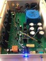
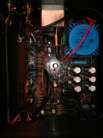
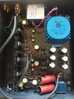
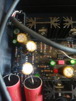
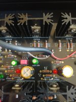
I do see some long capasator legs around the OP amp. Those legs will act as antenna and pick up noise. The problem sure is not the amp design or the parts kit. Then it need to be the work that has been done.
Hello 14071466d,
I would check the marked solderjoints (red arrows). And you should clean your pcb with some
isopropyl-alcohol or a windowalcohol and a toothbrush.
You can check your solderjoints with the DMM set to Ohm (resistance). Measure from the partleg (in the solderjoint) to the next partleg (along the traces of the pcb). Resistance should be a very low Ohm-reading.
I think you checked your voltages after the PSU ( you wrote +-17 V DC).
Perhaps others can chime in.
Cheers
Dirk
Attachments
yes +-17v is the voltage with loading after recertified regulated and filtering. I solder on both side and triple checked all the soldering pointsHello 14071466d,
I would check the marked solderjoints (red arrows). And you should clean your pcb with some
isopropyl-alcohol or a windowalcohol and a toothbrush.
You can check your solderjoints with the DMM set to Ohm (resistance). Measure from the partleg (in the solderjoint) to the next partleg (along the traces of the pcb). Resistance should be a very low Ohm-reading.
I think you checked your voltages after the PSU ( you wrote +-17 V DC).
Perhaps others can chime in.
Cheers
Dirk
I have installed small 100nF decoupling caps between +/- and gnd, as close as possible to the opamp.Hi @Gregje ,
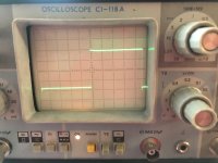
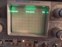
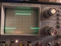
Keep in mind that those are widely zoomed transient response.
Looking at the complete 10kHz cycle, it definitely does not look slow:
https://www.diyaudio.com/community/attachments/scope_24-png.837240/
On this measurement, I scaled the pot to have unity gain, ie ~1.5Vp IN / OUT.
The 10kHz square wave at the phone socket looks pretty much the same as before. See pics below (different scales) except the last one (read on later).
Since I was messing around I though I will try feedback caps as well. I have found some 75pF in my boxes (the quality of these is not something I would like to put into Whammy, but good enough to do the scope experiments).
The result is in the last picture.
Attachments


Hello all,
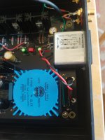
It's been awhile since on the website. I'm in a mad rush to get all the PASS amps and speakers (MA) finished due to my new "retirement" status. I've been diagnosed, finally, with stage 4 Prostrate Cancer. Terminal. Got the WHAMMY and B1 KORG finished. The Whammy is absolutely completely silent. No musick, cracks, pops, or buzz. The Korg has a proper green halo and this is as far as I can test without one of the amps finished.
The Whammy PSU tests came out within specs. Heat sinks are Pass perfect temp. Red LED's bright with D6 about 90 seconds behind D5 on shutdown. My soldering acceptable even for the shakes. I cut the grounds off pre-out in testing. I've read through all of 6L6's build guides (web and pdf) and searched all the threads and can't find a similar failure mode. Source is computer or android phone.
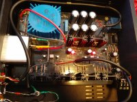
Is there any test points to measure in the chain before I order another complete kit to swap parts? Attached is the prerequisite poorly lit phone photo for judgement. I can provide other angles, of course. I've no idea if its a component failure or just me. Never had a DNF before.
THANKS,
Holzarbeiter
It's been awhile since on the website. I'm in a mad rush to get all the PASS amps and speakers (MA) finished due to my new "retirement" status. I've been diagnosed, finally, with stage 4 Prostrate Cancer. Terminal. Got the WHAMMY and B1 KORG finished. The Whammy is absolutely completely silent. No musick, cracks, pops, or buzz. The Korg has a proper green halo and this is as far as I can test without one of the amps finished.
The Whammy PSU tests came out within specs. Heat sinks are Pass perfect temp. Red LED's bright with D6 about 90 seconds behind D5 on shutdown. My soldering acceptable even for the shakes. I cut the grounds off pre-out in testing. I've read through all of 6L6's build guides (web and pdf) and searched all the threads and can't find a similar failure mode. Source is computer or android phone.
Is there any test points to measure in the chain before I order another complete kit to swap parts? Attached is the prerequisite poorly lit phone photo for judgement. I can provide other angles, of course. I've no idea if its a component failure or just me. Never had a DNF before.
THANKS,
Holzarbeiter
Attachments
Hey @Holzarbeiter, really sorry to hear about your diagnosis. Glad to hear you're making the most of your time doing things you enjoy!
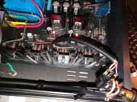
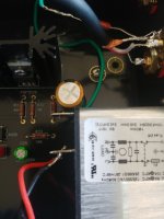
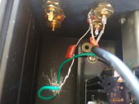
To answer your question, I believe it's possible you have accidentally mixed up the wiring on your TRS output jack. Is it a Neutrik Jack? If so, try swapping the preamp out and output wiring. You can double check your jack's datasheet.
Let us know if that changes things!
To answer your question, I believe it's possible you have accidentally mixed up the wiring on your TRS output jack. Is it a Neutrik Jack? If so, try swapping the preamp out and output wiring. You can double check your jack's datasheet.
Let us know if that changes things!
sp33ls,Hey @Holzarbeiter, really sorry to hear about your diagnosis. Glad to hear you're making the most of your time doing things you enjoy!
To answer your question, I believe it's possible you have accidentally mixed up the wiring on your TRS output jack. Is it a Neutrik Jack? If so, try swapping the preamp out and output wiring. You can double check your jack's datasheet.
Let us know if that changes things!
I can't get into the machine, restoration, shop to finish the aeroplane, race car and panel beating projects. Doing the Pass Amps at least I can sneak them into the bedroom (shop)! lifting a soldering iron is barely possible let alone a welding torch. 🙁
Took this long to switch out the wiring as you can see in attachment. I'm that slow. Yes, it's a Neutrik. Stock complete kit from the DiyAudio store. The problem remains, no sound at all into the Grado Headphones.
While on the poisons this is the best I can do.
Thanks so much for your help!
Holzarbeiter
Attachments
sp33ls,sp33ls,
I can't get into the machine, restoration, shop to finish the aeroplane, race car and panel beating projects. Doing the Pass Amps at least I can sneak them into the bedroom (shop)! lifting a soldering iron is barely possible let alone a welding torch. 🙁
Took this long to switch out the wiring as you can see in attachment. I'm that slow. Yes, it's a Neutrik. Stock complete kit from the DiyAudio store. The problem remains, no sound at all into the Grado Headphones.
While on the poisons this is the best I can do.
Thanks so much for your help!
Holzarbeiter
As you can see I soldered it back to original config. I'm doing this work to monitor my condition and failed. Have to do it again. 🙁 Proof Chemo is hard... I'll have to stop for awhile. Let you know asap.

Awesome, that's what I meant -- just had to swap sides for the connections on the output jack. 🙂sp33ls,
Tears!!! Bach 😍
sp33ls, Thankyou for being my eyes
BEST to you,
Holzarbeiter
How does it sound? I've found that the WHAMMY sounds incredible to my ears. Wayne is very generous.
In my defense symmetry subconsciously rules. Having the cables cross and the switch canted bugs me. That's just the way the case fits the board. Why I repeated my mistake. Could not hold the jack steady, dropping it and starting over brought me back on the same road. I should have known it's a switch. Needed to be wired as a switch. Could not see it until you graciously pointed it out. Took a month to build one resistor per hour at a time.Awesome, that's what I meant -- just had to swap sides for the connections on the output jack. 🙂
How does it sound? I've found that the WHAMMY sounds incredible to my ears. Wayne is very generous.
The WHAMMY is an instrument in it's own right! No noise floor, quieter then my grandfathers church allowing the full range of the Orgel to be heard. Can't wait to hear The Messiah by Bach. All the Cantatas as well. I didn't think I wanted to roll op amps until I heard the Oboe and Trumpet Stops on Vogel's Orgelwerke. Now I'll have to research that. Any recommendations? Pass Amps cured me from going to tubes. Wayne has brought about a very happy medium to explore that sound without breaking glass!
I don't understand some of the comments, problems, with some builds being noisy or not worthy of being considered against 'high end'. If someone in my condition can build it to play with absolutely authority FOR the Musick and not override it in any way, there is no excuse. It's that bloody good.😀
Wayne and Nelson with all the help from the forum esp. 6L6, and the Mighty Zen deserve all praise for their generosity. Jason et all. for keeping stock up. On a mission to burn that stock down until I can't hold the torch anymore.
Pass Dual Mono F6 and testing B1K next.
Thanks,
Holzarbeiter
be well, enjoy!
Thankyou Zen! Seems a linestage from Wayne is in order. In the months coming up after completing NP's amps I need to look at your contributions again. You were in the process of working out shipping to the US. Timeframe when AndrewT passed. I can't stop welding... Even though it's soldering, close enough. Will see if I can get that far.be well, enjoy!
Best, Dear Zen
Holzarbeiter
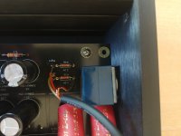
Your board looks greasy for some reason. Flux is good but use it sparingly.I am annoyed. I hate this kit. It just doesnt work. This is already the second set I bought from the store. Both set ends up in the problem which is all I can heard is 20% music and 80% noise. There was too many uncertainties in my first WHAMMY because I replaced all the component into expensive audiophile parts. It could be my own careless mistake messing thing up. For the second time, I used almost all the parts provided by the store and the result has no difference.
20% music and 80% noise.
I have checked the +17 and -17 voltage test for both times.
I have spent over 1500USD hoping to build one working whammy.
I have spent all of my patient and confidence in DIY.
I hate seeking help when facing difficulties.
Can anyone just tell me what the F is going on here.
Have you tried grounding the volume pot to the board? Sometimes the chassis grounding/earthing is high impedance so connecting the volume pot to the PCB grounding provides better connection.
Also the headphone out Ground with the screw looks very peculiar.
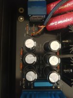
I also noticed your power capacitors are floating and aren't flush. The negative and positive rails also has different capacitors though I guess as long as they're the same rating it should be ok.
Where is your input Ground connected to? The point beside R39 2.2k is not connected.
Good evening,
Over this past week I assembled the Whammy. However, I inadvertently, switched Q1/Q3 with Q2/Q4. I un-soldered the mosfets, but by the time I had them out they were too deformed to use again, so I ordered replacements. After putting in the replacements and powering on for a listen I can hear music. However, voices sound faint with an echo (though instruments sound better) in both right and left channel. because it is in both, I am wondering if the replacement mosfets were correct. I ordered the following because the originals were discontinued.
https://www.mouser.com/ProductDetail/844-IRF9610PBF
IRF610PBF Vishay Semiconductors | Mouser
If these are incorrect, any suggestions for replacements?
Thanks.
No need to match hFE.
Honestly, I had something somewhat similar happen to me when I realized I wired my TRS jack up incorrectly. Also, check your signal ground
Honestly, I had something somewhat similar happen to me when I realized I wired my TRS jack up incorrectly. Also, check your signal ground
As I say, most human voices sound faint with an echo in both right and left channel. It's as if the singers are in a muted echo chamber. Conversely, some instruments seem to be on the foreground. this is particularly the case with stringed instruments. If the replacement Mosfets are the same as those original to the kit, then what could be the source of the issue? I measured V- at R13 pad and R14. Read -17V plus. I have replace the original input coupling capacitors but it did not change the sound. all resistors were sorted and placed correctly. I double checked all soldering joints. below are photos of the build.
Attachments
-
 20220420_074926.jpg458.9 KB · Views: 144
 -
 20220420_074631.jpg213 KB · Views: 142
 -
 20220420_074709.jpg205.1 KB · Views: 130
 -
 20220420_074649.jpg228.2 KB · Views: 127
 -
 20220420_074714.jpg226.8 KB · Views: 134
 -
 20220420_074642.jpg321.6 KB · Views: 130
 -
 20220420_074635.jpg304.3 KB · Views: 136
 -
 20220420_074654.jpg247.7 KB · Views: 138
 -
 20220420_074721.jpg235.7 KB · Views: 131
 -
 20220420_074639.jpg291 KB · Views: 148
- Home
- Amplifiers
- Pass Labs
- "WHAMMY" Pass DIY headphone amp guide