Thanks, sp33ls and KevinHeem.
I confirmed the specs for old and new mosfets are the same. The TRS jack appears to be wired correctly. However, I am not sure about the signal ground. the photos from the build guide for the wiring was not clear to me. additionally, I connected my ground wire directly to the chassis without a star ring terminal. also, the signal inputs to PCB are soldered from the top of the PCB inadvertently.
I confirmed the specs for old and new mosfets are the same. The TRS jack appears to be wired correctly. However, I am not sure about the signal ground. the photos from the build guide for the wiring was not clear to me. additionally, I connected my ground wire directly to the chassis without a star ring terminal. also, the signal inputs to PCB are soldered from the top of the PCB inadvertently.
Is your chassis ground connected directly with your IEC inlet GND on your ground lug (star washer is recommended)?
Then, is your signal ground connected to that with the 0.47uF (or similar) capacitor between them?
Uploaded a picture of mine. My wiring isn't nearly as clean, but this worked well for me (no noise, even at full volume) and may give you an idea on how I connected to GND (using pull down resistors for my pre-amp out).
Attachments

Thanks, sp33ls! This is extremely helpful. I think this is where my issue may be.
The photo is a little dark. Did you connect your signal ground to both right and left RCAs? it does not look like the RCA GNDs are bent toward one another. did you connect the two with a small wire? also where (which RCA) did you connect the black GRN wire that runs to the GRN on the PCB?
I have not done the pre-amp out but I am thinking this would not cause an issue with the signal.
Hi Speels,Is your chassis ground connected directly with your IEC inlet GND on your ground lug (star washer is recommended)?
Then, is your signal ground connected to that with the 0.47uF (or similar) capacitor between them?
Uploaded a picture of mine. My wiring isn't nearly as clean, but this worked well for me (no noise, even at full volume) and may give you an idea on how I connected to GND (using pull down resistors for my pre-amp out).
Just wondering did you use a 25k or 100k alps pot ?
- Dan
RCA left & right ground are connected together with a wire and then that is connected to the capacitor.
That black wire connected behind the Alps pot on the PCB is also connected to both RCA left & right ground.
You essentially want to have all signal ground be the same, and then all chassis to be the same, and these are separated (lifted) by the capacitor, if that makes sense.
I believe I used a 10k pot -- would have to double-check, but that shouldn't matter in this particular case.

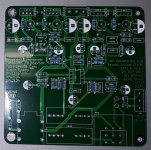
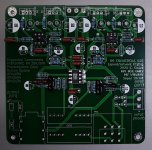
@Berkbear I assume you are building the "LED referenced" regulator config, in that case R9, 10 , 13 and 14 should not be populated. Refer to Step 8 in the guide linked at the beginning of this thread.As I say, most human voices sound faint with an echo in both right and left channel. It's as if the singers are in a muted echo chamber. Conversely, some instruments seem to be on the foreground. this is particularly the case with stringed instruments. If the replacement Mosfets are the same as those original to the kit, then what could be the source of the issue? I measured V- at R13 pad and R14. Read -17V plus. I have replace the original input coupling capacitors but it did not change the sound. all resistors were sorted and placed correctly. I double checked all soldering joints. below are photos of the build.
I also made this mistake though and I didn't notice any audible issues so this probably isn't your main problem. It's easy to get carried away stuffing all those resistors!
Thanks Speels, just wonderingRCA left & right ground are connected together with a wire and then that is connected to the capacitor.
That black wire connected behind the Alps pot on the PCB is also connected to both RCA left & right ground.
You essentially want to have all signal ground be the same, and then all chassis to be the same, and these are separated (lifted) by the capacitor, if that makes sense.
I believe I used a 10k pot -- would have to double-check, but that shouldn't matter in this particular case.
@sp33ls Thanks for the clarification. I tried to clean up my grounding on the input and added a terminal GRD (see attached). I also connected the pre-amp out (without resistors). I will not use the pre amp but wanted to wire it up in case it had some effect. Unfortunately, I damaged my silicone tip to my solder sucker, so I am in a holding pattern until a new one arrives.
Based on the clean-up I do not think it is a grounding issue as there is no hum. as I say the issue is in both channels and is best described as some sounds being muted, while others are not. Voices are often in the background while instruments are in the foreground. Sort of a reverse of what songs typically would sound like. It must have to do with the resistors or capacitors. I will go back through this thread to see if there are resistors that are miss labeled in this project. Unfortunately, I did not test them to verify value before I installed them.
@JermNZ Yes, I had R9, 10, 13 and 14 not installed when I originally heard the issue but install them thinking it may resolve the issue. I could not tell any discernable difference with or without them, but its hard to critically listen with the present issue.
Thanks for your help! Any other suggestions would be appreciated.
Attachments

Do you have left and right channels out of phase somewhere? As in, the plus and minus signal wires are flipped on one channel?
@A Jedi I could have channels out of phase. Where would be the likely spots for this? The photos of the project are on the bottom of p224 of this thread. My thought would be signal input at the RCA to the PCB and signal out from the PCB to the headphone jack. All four look correct; red being right channel and white being left, while GRN is the exposed wire around the two.
RCA -> pot -> board -> headphone jack are the ones I can think of. Basically everywhere that signal wires connect.
What voltage is your opamp seeing?
Have you tried swapping it out with another (unlikely, but worth a shot).
Have you tried swapping it out with another (unlikely, but worth a shot).
Are you able to verify that you're getting the expected voltage range on your opamp? That might help to eliminate other possibilities
How to I measure expected voltage range on my opamp?Are you able to verify that you're getting the expected voltage range on your opamp? That might help to eliminate other possibilities
Dear All,
just started building the complete kit bought at diyaudiostore. I apologize, I am sure the answer is already here, but I could not find it.
In the kit I found 4 220microF caps rated 50V and 2 220microF caps rated 25V, but on the board there are 6 220microF caps all rated 50V.
Looking at the pictures of the guide, I guess that the 25V caps can be C8 and C10, but am I right?
Thanks a lot
Renato
Looking at the pictures of the guide, I guess that the 25V caps can be C8 and C10, but am I right?
Simple answer is yes 🙂
I found the critical points to be grounding. In you pictures it seems you have not grinded away the black oxide on the aluminium cabinet where you have the ground connection. That oxide is basically not condutive and can generate a fair bit of noise. I had to grind away the oxide on the ground connection points, but also between other parts of the box, so that basically the whole box was properly connected together. That oxide basically prevents that. And created noise if i toched the box or the volume knob, even if I at first had ground away the oxide at the ground lugs, but that basically just grounded the back panel and left the rest of the box in limbo. Good luck!where is the critical points
I
- Home
- Amplifiers
- Pass Labs
- "WHAMMY" Pass DIY headphone amp guide