Did you forget to water it at least twice per day?! ;pHello guys,
I'm back here because of a big transformer problem.
After 4 months of beautiful work of my Whammy, now it seams completely dead.
1. Check your fuse(s) to see if any have blown
2. If fuse(s) are fine, try using a multimeter to [carefully] measure across one of those bridge diodes next to the transformer to see if they're receiving any voltage with the unit powered on
sp33ls I put it in the dishwasher once a week, just to be safe! 😛
It's unbelievable but the problem was in the wall socket, I used the multimeter to check 220 Volt (Europe) in the main power cable and it reads just 110V, I changed wall socket, I connected the Whammy and boom... now is on.
I did not imagine that the problem could be on the wall socket, never happened to me in my life... since now of course.
Thanks for your help, I'm going to investigate a little more on that socket.
Best!
YAY !! Thanks very much.. seasons greetings!these will do
cleaned and checked on JLCPCB routine
Do more measurements. Go forward in the "chain". Do you get voltage out of Talema transformer at secondary etc.....
Seems to be a power supply failure......is my best guess since it is 100% dead.
Seems to be a power supply failure......is my best guess since it is 100% dead.
anything from 10K to 100K will do
matter of Source Cojones (Rout) to drive the pot, having nothing with preamp itself
in principle, less KOhms , better - lesser influence of interconnect cables
matter of Source Cojones (Rout) to drive the pot, having nothing with preamp itself
in principle, less KOhms , better - lesser influence of interconnect cables
@dannybarry
simple as that - if you read some decent resistance on mains cable directly - means that cable, fuse, switch and primary of xformer are OK
if you read open circuit - check fuse, fuse holder, switch, mains cable , primary directly on pcb connections
if all that OK, power on, find appropriate pads in fron of diode bridge and check is there AC voltage
write here what you got
Anyone notice a relatively high DC offset with the Sparkos SS3602? When I use this opamp, I notice the DC offset starts around 0mV, but then steadily climbs until it reaches around 60mV a couple minutes after power on.
Dual OPA828 results in around 0.3mV, and OPA1612 is around 7mV.
Edit: just realized that the input stage of the Sparkos is a dual matched pair of NPN BJTs and not a FET. Well hmm... I guess 60mV DC isn't enough to cause any side effects, right?
Dual OPA828 results in around 0.3mV, and OPA1612 is around 7mV.
Edit: just realized that the input stage of the Sparkos is a dual matched pair of NPN BJTs and not a FET. Well hmm... I guess 60mV DC isn't enough to cause any side effects, right?
I'm assembling the new WHAMMY kit, but I'm confused with the 220uF capacitors. In the kit is 4x 220uF 50V caps and 2x 220uF 25V caps, but I see 6 places in the PCB/schematic that require 220uF 50V caps. Which locations are the 25V caps supposed to be used for? Are they all supposed to be 50V caps?
My kit was the same way. It doesn't really matter where you use the 25 volt caps, according to earlier posts in this thread.
One thing I wish I did was mount the caps by the op amp mount underneath the board, in order to have room for larger op amps
One thing I wish I did was mount the caps by the op amp mount underneath the board, in order to have room for larger op amps
Thanks, I was worried I had the wrong parts. That's an interesting idea about making room for the op amps.My kit was the same way. It doesn't really matter where you use the 25 volt caps, according to earlier posts in this thread.
One thing I wish I did was mount the caps by the op amp mount underneath the board, in order to have room for larger op amps
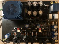
Hi -- I've followed your issue with the whammy build & I have a similar situation -- except I'm not as adept as most with DIY & have an issue trying to troubleshoot.I am settled. Thanks again. I used wrong side pin from the audio jack connector. Did not realize the insert - disconnect mechanism in the kit connector (checked my ACP+ and realized it...)
This kit came raw (1 bag of J/FET, 1 bag of OpAmp + 4N35, everyone else in one big bag). No packing list (matched to BoM and schema). Replaced power caps (blue vishay) and input coupler caps (grey film Vishay BC). From my understanding, the key of design is to provide a very clean power source in 3 levels and the rest is a straight forward amp.
I've gone through this twice -- with the same results ( two identical boards -- and two identical parts kits) -- when the first issue happened - I decided to get a new board rather that trying to remove all the components, although I salvaged the volume pot - & I took extra care with the soldering and board layout the 2nd time around ( which is why I'm so baffled at having the same issue again).
I've checked all my solder points with a DMM and confirmed there are no shorts anywhere - I've measured all the resistors on the board after they were installed to ensure they where labeled and installed properly & they all measure as they should with the exception of all the 10K resistors ( all of the DALE 1002F resistors only measure roughly 8.4K not 10K as spec'd ) - I've used the LED version for the power supply & both times - voltage checked out fine with the DMM before I began to stuff the board according to the guide
I've confirmed that the regulators & MOSFET pcs are in the correct pair orientation -- all diode and capacitor polarities are correct. I'm at a bit of a loss for the 2nd time around & I'm curious if you were able to determine what the most probable cause was of the extreme heat on the power supply 5.1 ohm resistors -- as I really would like to avoid starting all over again with a new board.
Do you think the 10K resistors might be an issue at only reading 8.5k ? --------- How can I properly trouble shoot this with a DMM without powering it on ? & is there a guide somewhere that tells me what readings I should be seeing on the various areas of the board to isolate the issue --------- as I'd like to salvage the project this time around.
Any guidance you can suggest would be greatly appreciated ------ the guide on the website is a few years old -- the board and the kit are the newest versions -- Is there anything that the guide overlooked relative to the new board and parts kit --- everything seemed fairly straight forward ( other than the confusion around missing bolts for the mosfets & the 25 v vs 50 v issue with the 220 uF caps - so I'm miffed at why I have the same overheating issue twice - with new parts. -- is this strictly related to the MOSFET's possibly not operation as they should ( I've confirmed there are no shorts on any of the mosfet pins)
I've attached a shot of the board in case I've overlooked something that's obvious to others
thanks a lot and seasons greetings -- ( My partner thinks I should be doing something other than this on Christmas day -- So I don't assume too many are reading this today )
Bart
Attachments
Hi -- I've followed your issue with the whammy build & I have a similar situation -- except I'm not as adept as most with DIY & have an issue trying to troubleshoot.
I've gone through this twice -- with the same results ( two identical boards -- and two identical parts kits) -- when the first issue happened - I decided to get a new board rather that trying to remove all the components, although I salvaged the volume pot - & I took extra care with the soldering and board layout the 2nd time around ( which is why I'm so baffled at having the same issue again).
I've checked all my solder points with a DMM and confirmed there are no shorts anywhere - I've measured all the resistors on the board after they were installed to ensure they where labeled and installed properly & they all measure as they should with the exception of all the 10K resistors ( all of the DALE 1002F resistors only measure roughly 8.4K not 10K as spec'd ) - I've used the LED version for the power supply & both times - voltage checked out fine with the DMM before I began to stuff the board according to the guide
I've confirmed that the regulators & MOSFET pcs are in the correct pair orientation -- all diode and capacitor polarities are correct. I'm at a bit of a loss for the 2nd time around & I'm curious if you were able to determine what the most probable cause was of the extreme heat on the power supply 5.1 ohm resistors -- as I really would like to avoid starting all over again with a new board.
Do you think the 10K resistors might be an issue at only reading 8.5k ? --------- How can I properly trouble shoot this with a DMM without powering it on ? & is there a guide somewhere that tells me what readings I should be seeing on the various areas of the board to isolate the issue --------- as I'd like to salvage the project this time around.
Any guidance you can suggest would be greatly appreciated ------ the guide on the website is a few years old -- the board and the kit are the newest versions -- Is there anything that the guide overlooked relative to the new board and parts kit --- everything seemed fairly straight forward ( other than the confusion around missing bolts for the mosfets & the 25 v vs 50 v issue with the 220 uF caps - so I'm miffed at why I have the same overheating issue twice - with new parts. -- is this strictly related to the MOSFET's possibly not operation as they should ( I've confirmed there are no shorts on any of the mosfet pins)
I've attached a shot of the board in case I've overlooked something that's obvious to others
thanks a lot and seasons greetings -- ( My partner thinks I should be doing something other than this on Christmas day -- So I don't assume too many are reading this today )
Bart
Sorry, ignore my help request --- I re-read the initial instructions & re-checked the MOSFET's & I do in fact have them in the wrong spots ( on both boards - reversed 610 vs 9610 ) -- I'm not sure this will fix my problem - but I've removed the heat sinks & MOSFETS -- I'm going to order new regulators - as I had to put a lot of heat and stress on these taking them out -- I'd rather not risk re-using them. I'm hoping this is the issue. -- But I'm still puzzled by the 8.5 k ohm reading on all the 10 k resistors..
You can never trust ohmmeter reading of resistors in circuit, as there are other components that are invariably in parallel with them. I'm pretty certain this isn't your problem. If concerned, lift one end and measure.
You can never trust ohmmeter reading of resistors in circuit, as there are other components that are invariably in parallel with them. I'm pretty certain this isn't your problem. If concerned, lift one end and measure.
I recommend caution here; in my own experience, bold statements & claims which include "never" and/or "invariably" are usually mistaken, and counterexamples are usually available and well known.
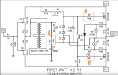
For example, Nelson Pass generously donated the schematic of his now-discontinued First Watt M2 amplifiier product, that retailed for USD 3000:
https://www.diyaudio.com/community/threads/official-m2-schematic.281520/
Examining Nelson's schematic, from a real-life + real-world amplifier: We immediately find three resistors whose only DC current path from one terminal to the other, is the resistor itself. An ohmmeter connected to the two resistor terminals, injects a DC current "I" into the network. This current flows in the resistor and nowhere else. So the meter's measured voltage "V" = "I" * Resistance, which is exactly as the ohmmeter designers assumed, and the ohmmeter's output display ( "V" / "I" ) is correct.
In other words, here are there counterexample when you can sometimes trust ohmmeter reading of resistors in circuit; sometimes there are no other components in parallel with a resistor-under-test. Not always, of course. But not never either.
_
Attachments
I wonder if the power output continues to increase all the way down to 14 Ohms, or if it starts to roll off by the time it gets to loads this low.I tested it into 32 Ohms and it is about 400 mW at low distortion. This will hurt your ears! It is capable of more than a watt into lower impedance loads.
I'm guessing that it's still over a watt at low distortion even at 14 Ohms tho.
At 14Ohms, power will most definitely be below 0.5Wrms, as my measurements in #3,093 indicate:I wonder if the power output continues to increase all the way down to 14 Ohms, or if it starts to roll off by the time it gets to loads this low.
I'm guessing that it's still over a watt at low distortion even at 14 Ohms tho.
(6.9Ohms output resistor)
300Ω - 9.8Vrms - 0.320W
68Ω - 8.75Vrms - 1.126W
43.7Ω - 6.4Vrms - 0.937W
18.5Ω - 3.05Vrms - 0.503W
- Home
- Amplifiers
- Pass Labs
- "WHAMMY" Pass DIY headphone amp guide