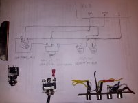
Am I thinking correctly with this setup? Will my diagram work? I want the 3prong 3way toggle to switch between headphone jack output and RCAs for use as preamplifier for ACA. Thanks for the help, I am learning a lot with this project.
You dont need a toggle switch. Just a switched headphone Jack. When you plug your headphones in the preamp output will be muted. Unplug the headphones and the preamp can be used. This is how I wired mine.
Thanks for the link to the part.I would like to get one of those eventually.
But for now I just have to use what i have. Just looking see if what I showed will work?
But for now I just have to use what i have. Just looking see if what I showed will work?

I finished this PCB and added some pictures on the empty space, it looks quite good.
PS: i crossed my NAME by white pen for Privacy.
There are two posts, which post should i join for my DIY ?
But for now I just have to use what i have. Just looking see if what I showed will work?
No. You don't have enough terminals on the switch to get both L and R switched, and the way you have it drawn L is always "on" to the 1/4" and the RCA.
You either need a DPDT switch or a switching headphone jack.
Ashleytt, I bought this row of 30 breakaway pins from Mouser
TS-132-G-AA Samtec | Mouser
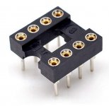
They fit beautifully into the SOIC-to-DIP8 adapter PCB sold by Sparkfun (link). After soldering the IC chip to the adapter board, then soldering the pins to the board (broken off as two rows of 4 pins/row, naturally), the entire assembly fit perfectly into a DIP socket. I prefer the sockets with "milled" pins as shown on the attached image below.
_
TS-132-G-AA Samtec | Mouser
They fit beautifully into the SOIC-to-DIP8 adapter PCB sold by Sparkfun (link). After soldering the IC chip to the adapter board, then soldering the pins to the board (broken off as two rows of 4 pins/row, naturally), the entire assembly fit perfectly into a DIP socket. I prefer the sockets with "milled" pins as shown on the attached image below.
_
Attachments
Don't forget to put 2.2k in series with the input.
Thx for your reminder.
I am so blue now, I have a big mistake, I forgot to add the mounting drill holes in the four corners, caused machine to open big hole in these corners. Sad
Thanks so much Mark! I searched aliexpress and ebay for these pins and got nothing! I'll give these a try and report back! Cheers!Ashleytt, I bought this row of 30 breakaway pins from Mouser
TS-132-G-AA Samtec | Mouser
They fit beautifully into the SOIC-to-DIP8 adapter PCB sold by Sparkfun (link). After soldering the IC chip to the adapter board, then soldering the pins to the board (broken off as two rows of 4 pins/row, naturally), the entire assembly fit perfectly into a DIP socket. I prefer the sockets with "milled" pins as shown on the attached image below.
_
i ordered some components for modification.

6 different Opamp which included AD823

2 type of output transistor. 2013+313 was matched

RIFA PHE450 MKP 224 0.22UF 630V VS WIMA 0.22uF 300v
WIMA 1UF/100V MKS4 VS ERO MKT 250V 105 1UF
i dont know the 0.22uf and 1uf which type is better.

Here is a big question, i ordered 3 types of 220uf, but nichicon and SIC SAFCO are too big for installation, only Panasonic FC 220uf is suitable for this board.
Nichicon BP 220uf/50V got the ESR is 0.1324r @120Hz
SIC SAFCO 220uf/100V got the ESR is 0.148r @120Hz, bur the true value is 280uF, is it OK for use ?
May i know where should i install nichicon BP or SIC SAFCO is better as i can't install all of this on the board.
6 different Opamp which included AD823
2 type of output transistor. 2013+313 was matched
RIFA PHE450 MKP 224 0.22UF 630V VS WIMA 0.22uF 300v
WIMA 1UF/100V MKS4 VS ERO MKT 250V 105 1UF
i dont know the 0.22uf and 1uf which type is better.
Here is a big question, i ordered 3 types of 220uf, but nichicon and SIC SAFCO are too big for installation, only Panasonic FC 220uf is suitable for this board.
Nichicon BP 220uf/50V got the ESR is 0.1324r @120Hz
SIC SAFCO 220uf/100V got the ESR is 0.148r @120Hz, bur the true value is 280uF, is it OK for use ?
May i know where should i install nichicon BP or SIC SAFCO is better as i can't install all of this on the board.
Last edited:
I don’t think there’s a much better electrolytic made than the FC. All the factory Pass Labs products are filled with them.
+ 1
The Panasonic FC are my standard go-to electrolytic capacitors for a few years now. Have always been very happy with their performance.
Best regards, Claas
The Panasonic FC are my standard go-to electrolytic capacitors for a few years now. Have always been very happy with their performance.
Best regards, Claas

Thx 6L6 and chede solved my question. I will use FC in my board.
The 3300uf/50V i will use NipponChem KY series. I tested this cap then got the size is 3200uf and ESR is 0.0424R, the result is good.
hello,
when you measure the distortion of a headphone amp, what are you using as a load and under which voltage?
when you measure the distortion of a headphone amp, what are you using as a load and under which voltage?
Hi there. I'd like to know how to calculate the power outputs (mW) of Whammy to the phones I'm using: 14ohms, 46ohms, 250ohms and 300ohms. I'm using the default 17v rails and 60mA bias. TIA!
Hi there. I'd like to know how to calculate the power outputs (mW) of Whammy to the phones I'm using: 14ohms, 46ohms, 250ohms and 300ohms. I'm using the default 17v rails and 60mA bias. TIA!
Power = Voltage * Current
Current = Voltage / Resistance
Therefore
Power(in watts) = Voltage^2 / Resistance
The typical max volume level is 2v, and going off that:
2v^2 / 14ohms = 286mW
2v^2 / 46 = 143mW
2v^2 / 250 = 16mW
2v^2 / 300 = 14mW
That would be peak, not RMS. Divide by the square root of 2 to get an approximation of the RMS, if that is what you want.
From what I understand, the 17v rail is mostly for the op amp, to allow it to swing further, to keep the output from dropping lower than the input without clipping.
Last edited:
I tested it into 32 Ohms and it is about 400 mW at low distortion. This will hurt your ears! It is capable of more than a watt into lower impedance loads.
fwiw I spent an enjoyable couple of hours with the Whammy driving my 12" 100db 8 Ohm open baffle drivers and while they do benefit from a bit more oomph it was still very much an enjoyable listen with a clean & detailed presentation. The Whammy didn't seem to be stressed the heat sinks were no warmer than normal and the transformer (22v) stayed cool to the touch during that time.
Normally I use a 2W Set amp.
Normally I use a 2W Set amp.
- Home
- Amplifiers
- Pass Labs
- "WHAMMY" Pass DIY headphone amp guide