I For preamps, it's often the pot, if you want a really good one.
Precisely, as you speak of the volume potentiometer I'm wondering a little about which to take. to be frank I would like it to be the best possible but with a fairly large range of use and without exceeding 100 euros.
i saw this one what do you think ?
Module Controle de Volume a Relais Selecteur de Source RCA 50K - Audiophonics
IMO, it's not worth overthinking it. Are there [very subtle] differences between channels with tracking..? Sure, usually like a few mV. Can you hear it with a quality pot? No, at least my 30 year old ears can't -- and they also couldn't when I was 25. 🙂 But, YMMV.
Plus, you may have to perform some special tweaks (mainly wiring correctly) to get it to work.
The ALPS that is suggested in the BOM is my recommendation.
The ALPS is good. I used an Audio Note in one build, and it was slightly better for not much more money. I've also used an Aleph P-like control I got on EBay, which sounds great but is annoying to use, since it needs power (and it has some issues when the pot gets into certain areas). The Audiophonics looks quite similar to that.
I'm now using a Khozmo stepped attenuator, and it is very good, but pricey.
I'm now using a Khozmo stepped attenuator, and it is very good, but pricey.
I'm now using a Khozmo stepped attenuator, and it is very good, but pricey.
Khozmo is very highly regarded amongst builders. This would be my vote if you wanted to go with fancy attenuation. But, of course, you pay for that luxury. 🙂
Otherwise, I thought of this one:
Potentiometre Commute Stereo Logarithmique 22 Positions Resistances CMS Axe Crante 50K Ohm - Audiophonics
On the other hand I want to put the board in a longitudinal position, that is to say that the entry of the pot would be on the right of the box and therefore the pot would not be directly welded to the board.
Are there any rules to respect, such as the length of the cables, the earthing of the pot as it is not directly connected to the chassis or others?
however it is the range of use which is also important for me because I need to be able to regulate the volume quite finely because I intend to use it also as a preamplifier. My wife works nights and therefore I need to be able to adjust the volume without waking her up, hence my question: would 22 notches be enough?
that interests me strongly, because I could mount it myself. do you know if there are explanatory supports? in asymmetric stereo there is only one need for one relay card if I understood correctly?
but in any case thank you for the info because I did not know
but in any case thank you for the info because I did not know
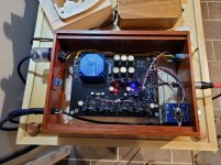
I think those may be the incorrect resistors, I believe they should be 1/2 W rated or larger.
Also, check the orientation of your diode at D7, it looks like it is the wrong way around, hard to see in the photo though.
Pictures :
Check the diode at the top after the regulator as it appears to be in backwards.
--Tom
Step 1 done then! Good luck with the rest. I can assure you that you'll find it worth the effort. It's no exaggeration to say that the Whammy competes admirably with the best headphone amps out there.
We've all been newbies once! 🙂
One suggestion: take a look at Jim's build guide as you work your way through the build. He has clear photographs and documentation of each phase, so you can check the orientation of caps/diodes/etc... I've built three of these and I still keep his build guide open because even after checking values/part types carefully, I've still been dyslexic a few times. A quick look at the picture is all I need sometimes to realize it, and I do that BEFORE I solder anything down.
WHAMMY headphone amplifier - diyAudio Guides
--Tom
Otherwise, I thought of this one:
Potentiometre Commute Stereo Logarithmique 22 Positions Resistances CMS Axe Crante 50K Ohm - Audiophonics
On the other hand I want to put the board in a longitudinal position, that is to say that the entry of the pot would be on the right of the box and therefore the pot would not be directly welded to the board.
Are there any rules to respect, such as the length of the cables, the earthing of the pot as it is not directly connected to the chassis or others?
If you use something other than the ALPS pot, then the best thing to do is to run the input cables directly to the pot, and bypass the connection on the board. Then run the output of the pot to the CENTER pads where the pot would go, and the ground 'output' from the pot to the LEFT pads (looking at the board from the front). The RIGHT pads will then be unconnected: those are the output from the board to the pot. (The grounds from the input jacks can still go to the same place on the board.)
This skips the traces on the board, gives you one fewer mechanical connection, and makes everything quite a bit neater. (I've built four Whammies now and have tried a lot of different arrangements!)
The only thing you need to consider here is the 2.2K input resistors on the board. Wayne said in an earlier post (I asked about this) that, in most cases, it's fine just to leave them out. In the end, though, I just soldered them to the pot input and connected the input cables to the resistor. The Whammy already has a lot of gain and leaving them out could make that worse. Use a bit of heat shrink over the connection to the resistor and it's very solid and safe.
You can see it in the picture reasonably well. On the pot, the inputs are the bottom; the output above that; the ground outputs are hidden under the black wire.
You should run a wire from the pot body to earth ground. In the picture, that is the thin blue wire.
Attachments
Last edited:
that interests me strongly, because I could mount it myself. do you know if there are explanatory supports? in asymmetric stereo there is only one need for one relay card if I understood correctly?
but in any case thank you for the info because I did not know
If you are asking about the Twisted Pear Joshua Tree, the best source of documentation for their old projects is the Forum for support. One relay card, one controller, one volumite for single ended.
Hi,
I wanted to thank Rikiheck and Jermnz again because thanks to them my psu works.
Like a perfect beginner idiot I had put 3 diodes upside down and resistors not suitable for the CRC.
I would pay more attention to the rest. The new test went well and the measurements are correct. 😀
I even started to fill in the rest 🙂
No worries, I'm also far from an expert, just learnt from making similar mistakes! Glad you figured it out. 🙂
We've all been newbies once! 🙂
One suggestion: take a look at Jim's build guide as you work your way through the build. He has clear photographs and documentation of each phase, so you can check the orientation of caps/diodes/etc... I've built three of these and I still keep his build guide open because even after checking values/part types carefully, I've still been dyslexic a few times. A quick look at the picture is all I need sometimes to realize it, and I do that BEFORE I solder anything down.
WHAMMY headphone amplifier - diyAudio Guides
--Tom
The worst part is that I just had the guide in front of me. Well, on the other hand I was outside on my terrace on a small table and that I could not have everything in front of me at the same time. But I'll do it differently. Thanks for the wise advice.
If you use something other than the ALPS pot, then the best thing to do is to run the input cables directly to the pot, and bypass the connection on the board. Then run the output of the pot to the CENTER pads where the pot would go, and the ground 'output' from the pot to the LEFT pads (looking at the board from the front). The RIGHT pads will then be unconnected: those are the output from the board to the pot. (The grounds from the input jacks can still go to the same place on the board.)
This skips the traces on the board, gives you one fewer mechanical connection, and makes everything quite a bit neater. (I've built four Whammies now and have tried a lot of different arrangements!)
The only thing you need to consider here is the 2.2K input resistors on the board. Wayne said in an earlier post (I asked about this) that, in most cases, it's fine just to leave them out. In the end, though, I just soldered them to the pot input and connected the input cables to the resistor. The Whammy already has a lot of gain and leaving them out could make that worse. Use a bit of heat shrink over the connection to the resistor and it's very solid and safe.
You can see it in the picture reasonably well. On the pot, the inputs are the bottom; the output above that; the ground outputs are hidden under the black wire.
You should run a wire from the pot body to earth ground. In the picture, that is the thin blue wire.
So I think I understood what you are explaining to me but I am a beginner and I prefer to stay on the original connections because I am afraid of making a mistake somewhere.
on the other hand if I wire the pot with short shielded cable, as close as possible to the board and that I wire the pot to the chassis ground on the rca input with the small capacitor would that be okay? the pot would be on a support with an extension of course.
If you are asking about the Twisted Pear Joshua Tree, the best source of documentation for their old projects is the Forum for support. One relay card, one controller, one volumite for single ended.
Ok I found it. I will be able to get information from them thanks
No worries, I'm also far from an expert, just learnt from making similar mistakes! Glad you figured it out. 🙂
in any case you are maybe not an expert in electronics but in design you cannot say the same thing because your whammy is beautiful and well built.
So I think I understood what you are explaining to me but I am a beginner and I prefer to stay on the original connections because I am afraid of making a mistake somewhere.
on the other hand if I wire the pot with short shielded cable, as close as possible to the board and that I wire the pot to the chassis ground on the rca input with the small capacitor would that be okay? the pot would be on a support with an extension of course.
I'd wire the pot to the other side of the cap.
Note that, in wiring the pot to the board, you basically have to do the same thing I described. You just have another wire: the one for the input to the pot.
Also, adding to what others have said, THE most helpful thing for me has been to test every resistor and cap before it goes onto the board to make sure it is the right value. This saves all kinds of headaches.
NJM7815FA-ND & NJM7915FA-ND are both obsolete.
MC7915CTG is currently on backorder. Can MC7915ACTG be substituted? Only difference appears to be output voltage tolerance 4% (BOM P/N) vs. 2%.
MC7915CTG is currently on backorder. Can MC7915ACTG be substituted? Only difference appears to be output voltage tolerance 4% (BOM P/N) vs. 2%.
Any cooking grade version of the 7815 and 7915 is fine. The NJM's were 1.5 amp rated but any standard 1A version is OK as the current draw is way below that level.
Just buy whatever is in stock. Voltage tolerance makes zero difference to the design.
Just buy whatever is in stock. Voltage tolerance makes zero difference to the design.
- Home
- Amplifiers
- Pass Labs
- "WHAMMY" Pass DIY headphone amp guide