Do these drops happen on headphones? I ask because I made this into a headphone amp + pre with RCA outputs. I had a small problem with the switching headphone plug that was making irregular contact. Headphone always worked, but RCA outputs where presenting drops.Hi everyone!
Have been having irregular drops in my left channel for about a week now. The amp itself is well over 200h played with no problems.
DC offset on both channels is 14 mV when working normally, measured the left channel when it droped and it was 8 mV left ch. to ground.
Powersupply seemed fine.
Have tried two opams (OPA2134 and the RC4580)
Any tips? I'm thinking a cold solder would have made its presence earlier.
Fixing the contacts that were remaining open upon headphone removal fixed the drops.
Could this be your case?
Rafa.
you guys are having way too much fun.
I've never played with opamps, testing with headphones would be quite an enlightening process to compare the differences.
I am tempted.
I've never played with opamps, testing with headphones would be quite an enlightening process to compare the differences.
I am tempted.
Start slowly. Play with opamps in the Tucson daughter cards of your M2x power amp. Remember that (a) the socket on Tucson accepts single opamps, i.e., one amplifier per DIP-8 package; (b) the sockets on WHAMMY accept dual opamps, i.e., two amplifiers per DIP-8 package; (c) the pinout of a single opamp is different from the pinout of a dual opamp; even the supply pins are different
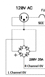
Here is a ground isolation circuit. The most important thing is to get a good hard earth ground to your chassis like Jim (6L6) stated. Remember anodizing is insulating so scrape and check with a meter. This circuit will help prevent ground loops yet carry fault currents.
To me this looks like a better method of isolating ground loops in a dual mono single chassis setup compared with a couple 20 Ohm thermistors.
Is that a fair assessment?
One per channel
I couldn’t wait for the pcb to arrive so I started the project with parts I had already laying around. I made this one dual op amp because I had a couple of opa604’s and will do tests with opamps like the AD797, OPA1611.
Have to finish the housing (cosmetic), arrange the wiring and replace the potmeter with a blue Alps potmeter.
For now I’m listening with a HD6xx headphone, the thing is death silent, no hum whatsoever. Dynamic, open, detailed. I could listen for hours. Will do some comparison (by ear) with my Sjostrom QRV08 amp.
3kes, did you ever get yours compared to the Sjostrom amp?
Where is this ground isolation circuit posted?Originally Posted by wayne
Here is a ground isolation circuit. The most important thing is to get a good hard earth ground to your chassis like Jim (6L6) stated. Remember anodizing is insulating so scrape and check with a meter. This circuit will help prevent ground loops yet carry fault currents.
Checked more than 20 pages and did not see it 😱
Edit: ok, got it. Did not know I just have to click the small arrow near the name.
Yes it also has been UL, CSA, etc tested.
That's great to know.
When I have seen a bridge used to isolate circuit 0V from chassis earth, the chassis earth was connected at the centre of the bridge so that current travels when the forward voltage of the diode is exceeded. An example is attached.
In your circuit current passes through the first diode when the forward voltage is exceeded, then it must exceed the reverse voltage of the second diode in series.
Before I start using this everywhere, is this the correct orientation of the bridge?
I'm assuming there is no mistake here. If there is a fault condition and current flows through the diodes, will the diode that is reverse biased fail and the bridge need replacing?
I am not sure what to expect if the reverse voltage of a diode is exceeded, having never operated a diode like this.
Attachments
Also, i wanna try using bjt outputs such as MJE2955/3055 pair. Is there anything on the circuit i should change?
That's great to know.
When I have seen a bridge used to isolate circuit 0V from chassis earth, the chassis earth was connected at the centre of the bridge so that current travels when the forward voltage of the diode is exceeded. An example is attached.
In your circuit current passes through the first diode when the forward voltage is exceeded, then it must exceed the reverse voltage of the second diode in series.
Before I start using this everywhere, is this the correct orientation of the bridge?
I'm assuming there is no mistake here. If there is a fault condition and current flows through the diodes, will the diode that is reverse biased fail and the bridge need replacing?
I am not sure what to expect if the reverse voltage of a diode is exceeded, having never operated a diode like this.
This is a little different than the circuit I had posted. In the one I had shown before there is two diode drops and you won’t exceed reverse voltage because the other diodes will turn on. The circuit must pass twenty amps and blow a fuse or breaker that’s why a thirty five amp bridge is used. It’s also in our stock room.
I had this exact thing happen to me when I started rolling OpAmps. The culprit was the DIP8 connector and making sure the chip's pins were spread sufficiently to press outward against them to make contact. Some OpAmps came packaged such that their pins were allowed to bend. I also had this happen specifically when I used the Burson and SparkOS Labs discretes as their pins are the round/rigid type and there the issue was again the DIP8 connector not making solid contact on one of the channel's i/o pins.
--Tom
--Tom
Do these drops happen on headphones? I ask because I made this into a headphone amp + pre with RCA outputs. I had a small problem with the switching headphone plug that was making irregular contact. Headphone always worked, but RCA outputs where presenting drops.
Fixing the contacts that were remaining open upon headphone removal fixed the drops.
Could this be your case?
Rafa.
This is a little different than the circuit I had posted. In the one I had shown before there is two diode drops and you won’t exceed reverse voltage because the other diodes will turn on. The circuit must pass twenty amps and blow a fuse or breaker that’s why a thirty five amp bridge is used. It’s also in our stock room.
So that vertical black line through the bridge is actually an electrical connection, allowing an electrical path to the other forward biased diode?
Please say yes. My brain is straining hard core. Actually don't say yes if that's wrong. Hahahahaha
I will attach the circuit again.
Attachments
Last edited:
So that vertical black line through the bridge is actually an electrical connection, allowing an electrical path to the other forward biased diode?
Please say yes. My brain is straining hard core. Actually don't say yes if that's wrong. Hahahahaha
I will attach the circuit again.
Alternatively you could rotate the bridge anticlockwise 90 degrees.
Power supply debug
I hope someone can help me. I'm building the board with the LED voltage reference and powered it up for the first time to test. The LEDs didn't light and I measured about+/- 37V on the rails. Checked the polarity of the caps and diodes and all were correct so the main thing I was left with was that I put the LEDs in backwards. That would obviously explain them not lighting up but would that explain the voltage?
Also, when I went to unsolder the LEDs I got sparks when I accidentally shorted the leads with the soldering iron tip. This was after the board had been disconnected and left sitting for several hours. I'm measuring about 23V across the leads of the big filter caps. Have tried grounding each side of the cap but haven't tried shorting the leads. I
I'm reluctant to do any further diagnostics on the LED while I still have these voltages. Any help or advice will be appreciated!
Hold a 3W, 1 Ohm resistor across terminals of each cap to drain the current out of them
Thanks! That did the trick. LEDs were in backwards as I suspected.

Plug the LED into your Mega328 component tester that you bought on eBay.
During testing, the LED will blink a couple times while the software figures out which pin does what, and while it measures Vf and Cj. When the LED blinks you will be able to see its illumination color --- which is super handy when your LED has a water clear body, and you can't tell by looking whether it's supposed to glow red, blue, green, amber, etc.
The Mega328 will tell you which pin is the LED anode (positive terminal) and which pin is the LED cathode (negative terminal). Lift it out of the tester, stuff into the PCB, bend leads, and solder. Errors eliminated!
Don't yet own a Mega328?? Get one! I prefer to have an acrylic case surrounding mine (USD 6.00 more on eBay) but that's a personal preference.
- Home
- Amplifiers
- Pass Labs
- "WHAMMY" Pass DIY headphone amp guide