I wanted instant-on, instant-off behavior from my front panel LED, so I connected it straight to the AC from the transformer (with a couple of other safety items). It did exactly what I wanted: no graaaaaaaaadual dimming as the supply filter caps slooooooowly discharge.
See post #1530 of this thread for a photo.
See post #1530 of this thread for a photo.
I wanted instant-on, instant-off behavior from my front panel LED, so I connected it straight to the AC from the transformer (with a couple of other safety items). It did exactly what I wanted: no graaaaaaaaadual dimming as the supply filter caps slooooooowly discharge.
See post #1530 of this thread for a photo.
This is an awesome idea and even I have some 1N4148 diodes and I wanted to use this logic to power the front panel LED switch 🙂
So from the pic how did you connect the diode in series to the hot AC wire (I meant the anode/cathode) and I think I can use a resistor of like 470R in series with the neutral AC wire or is it too low as I do not want a bright LED. I have couple of amps with 0-12VAC secondary which I usually use to power the speaker protection board. I intend to use this AC secondary winding for the LED.
Thanks
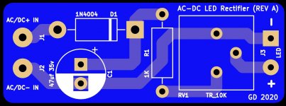
That's what I made these for.... 🙂 You can either take straight from the AC or from the DC side of the circuit. And for those with OCD, it looks neater. These also have a trim pot so you can adjust the brightness of the LED on the fly too 🙂
Attachments

Mark
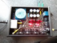
Thank you for picking up this enquiry - very much appreciated. Sounds an excellent solution. A little difficult to see from the image as the components are sleaved - So if I can perhaps get this straight - you made your connection straight to the transformer secondary +ve & -ve terminals with a 1N418 diode connected the anode of the LED. Can I perhaps enquire what resistor value you used on the cathode of the LED and the return to the secondary.
Many thanks for your help and support with this.
Best wishes
Niall
Hello guys, hope all of you are ok and healthy,
Being relatively new and not very experienced with electronics, I would like to ask a question.
Is there a difference if, C12 C17 C22 C25 C26 C27 are polar or bipolar? Is there a specific reason to help me choose the right part?
I will use the ad823anz as opamp is it related?
Thank you very much.
Being relatively new and not very experienced with electronics, I would like to ask a question.
Is there a difference if, C12 C17 C22 C25 C26 C27 are polar or bipolar? Is there a specific reason to help me choose the right part?
I will use the ad823anz as opamp is it related?
Thank you very much.
Dear Whammy Builders,
I wanted to get some feedback on a behaviour of my Whammy before I button up everything. There are three observations where I am curious about some feedback:
1. D6 lights up after switching on, but dimms down after half a second. D6 is darker when I leave the Whammy on
2. Noise. Whammy is buzzing, when I turn the Volume Pot the noise increases until I have reached 2/3 of the potentiometers capacity, at this point noise drops suddenly and increases again. When I reach 3/3 (turned to the right side as much as possible) the noise goes away. Is that a grounding issue and should go away with proper grounding in the case?
3. Offset. I have an offset of 0,08 mV left and -1,14 mV right. Both values are very low, but very different channel by channel. What can I try to get to the same levels both sides?
Some random measurements (all to ground):
R13: 5,69V
R26: 5,38V
R19: 5.64V
R11: 5,33V
R14: 16,87V (not stuffed) measured on the hole closer to the volume pot
R10: 16,44V (not stuffed) measured on the hole closer to the volume pot
D6: 1,73V
D5: 1,76V
I use a 15V Trafo, and stuffed the LEDs but left out R9, R10, R13, R14.
I've attached also a Youtube link to show the dimming of the LED. Many thanks for reading.
YouTube
Best, tom
According to the theory, bipolars have lower distortions. Cyril Bateman's Capacitor Sound articles | Linear Audio NL
I use DIY PCBs for my WHAMMY - so I use bipolars and film capacitors in parallel.
But I think it's more a matter of taste - it has not yet been proven whether taht anyone will hear the difference in blind test
I use DIY PCBs for my WHAMMY - so I use bipolars and film capacitors in parallel.
But I think it's more a matter of taste - it has not yet been proven whether taht anyone will hear the difference in blind test
In my experience diodes have to be matched (just measure voltage drop across resistor and 9V battery with diode connected) if you want them to be the same brightness.
My whammy also have similar DC offset ....at least-little more in one channel..i think its depend on opamp. 1.x mV- nothing to worry about.
My whammy also have similar DC offset ....at least-little more in one channel..i think its depend on opamp. 1.x mV- nothing to worry about.

Tom - your DC offset is 0.08mV ? (zero decimal zero eight millivolt) and -1.12mV on the other side? That’s absolutely fantastic performance, and about as low as anybody has ever achieved.
Thanks for the quick feedback. Yes, overall the DC offset looked very very nice, the difference between the channels was interesting. And yes, I can confirm at least, that the mentioned values where those which I've seen on the meter. 🙂
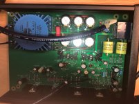
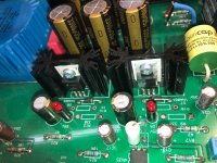
Please find attached some pictures. Many thanks again for your help!
Please find attached some pictures. Many thanks again for your help!
Attachments

Remove C7 and C2.
Remove the plastic bezel from the front of the chassis. Sand or scratch off the anodizing on the front plate where the pot touches it and where the front panel meets the sides of the chassis to make the chassis parts all at the same electrical potential.
Need to see the back panel.
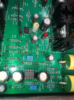
Do you know the exact manufacturer/series of resistors? I ask because the color bands are clearly legible against their background in photos... that’s really helpful! I need to try them.
Remove the plastic bezel from the front of the chassis. Sand or scratch off the anodizing on the front plate where the pot touches it and where the front panel meets the sides of the chassis to make the chassis parts all at the same electrical potential.
Need to see the back panel.
Do you know the exact manufacturer/series of resistors? I ask because the color bands are clearly legible against their background in photos... that’s really helpful! I need to try them.
Thanks! I removed today C2 and C7 and scratched off the anodising. No buzzing or humming anymore --> it is now dead quiet even with highest amplification; Even with unfinished case and the wildest cabling you can imagine.
DC Offset left: 0,11mV
DC Offset right: -1,08 mV
Will post pictures later. What would you recommend. Leave it as it is, or try to get to equal measurements for both channels (Supply Voltage and DC Offset)?
The resistors I've used are Takman REY Metal Film. I love them. 🙂
Best, tom
DC Offset left: 0,11mV
DC Offset right: -1,08 mV
Will post pictures later. What would you recommend. Leave it as it is, or try to get to equal measurements for both channels (Supply Voltage and DC Offset)?
The resistors I've used are Takman REY Metal Film. I love them. 🙂
Best, tom
Last edited:
Fantastic news! Button it all up and enjoy!
I believe your offset is the least ever recorded. Don’t do anything, that little is absolutely inconsequential.
I believe your offset is the least ever recorded. Don’t do anything, that little is absolutely inconsequential.
Thanks! I removed today C2 and C7 and scratched off the anodising. No buzzing or humming anymore --> it is now dead quiet even with highest amplification; Even with unfinished case and the wildest cabling you can imagine.
DC Offset left: 0,11mV
DC Offset right: -1,08 mV
Will post pictures later. What would you recommend. Leave it as it is, or try to get to equal measurements for both channels (Supply Voltage and DC Offset)?
The resistors I've used are Takman REY Metal Film. I love them. 🙂
Best, tom
I am sorry if I missed it, but which op amp are you using? I have noticed the biggest change in DC offset when swapping op amps.
I use an OPA2604.
I have one question. Can you explain why C2 and C7 may have caused the buzzing, I assume that the two caps were the cause of the buzzing, as the case is still not connected to earth?
Best, tom
I have one question. Can you explain why C2 and C7 may have caused the buzzing, I assume that the two caps were the cause of the buzzing, as the case is still not connected to earth?
Best, tom
- Home
- Amplifiers
- Pass Labs
- "WHAMMY" Pass DIY headphone amp guide