Sorry, what I meant is that you can bridge the positive and negative outputs of the pcbs to have the common return path. And than take the remaining +/- output. Without changing the design of the board itself.
Doing rhe pcb redesign is a different story.
You can have a look at meldano's universal psu in bridged mode as a reference
Doing rhe pcb redesign is a different story.
You can have a look at meldano's universal psu in bridged mode as a reference
Last edited:
I only have single rail positive at the moment. I'll be getting dual rail boards manufactured soon. Are you looking for positive/negative dual rail or positive/positive?
For the dual rail I am looking for positive/negative and for the single rail for positve.
Sorry, what I meant is that you can bridge the positive and negative outputs of the pcbs to have the common return path. And than take the remaining +/- output. Without changing the design of the board itself.
Doing rhe pcb redesign is a different story.
You can have a look at meldano's universal psu in bridged mode as a reference
I did a search and the Universal one he has takes two transformers and looks like it can handle upto 8 rails. Bridging the positive and negative simply doubles the voltage so would be no good. I guess you can reverse the polarity on the negative rail so you use the ground as positive and the negative as a ground if that makes sense. That will measure on a multimeter then as a positive voltage.
If we had two pairs of outputs one for each psu. Lets assume both psus have similar output equal to +V:
+1 ,-1, +2,-2
Say we jumpered
-1,+2, creating ~0
Than take the output from 1+ and common 0, you will have +v output of the first psu.
-2 and common 0, we will have a -v output of the second psu
+1 ,-1, +2,-2
Say we jumpered
-1,+2, creating ~0
Than take the output from 1+ and common 0, you will have +v output of the first psu.
-2 and common 0, we will have a -v output of the second psu
Here's my WHAMMY. Thanks to Wayne for a fun project! 
Thanks to Jim (6L6) for the great build guide and parts list!
Not that it matters even the slightest bit when the lid is on, I didn't like the way the input and output wires crossed back and forth so I decided to run mine under the board. I considered drilling a hole in the big empty space at the back for output but couldn't decide if I was going to try and fit a big fat switched/filtered/fused Schaffner power inlet module and went with the $ friendly option at the end. Instead of drilling through the middle of the board - because I couldn't see any traces/tracks due to the black silk screen (can't see throught it), I decided to just drill through the mounting hole instead. One in the front for the output and then one in the back. It made connecting the inputs a bit tricky but not a big problem.
On the front, I ordered a black Neutrik locking connector but again, decided to go with the $ friendly option but mostly because I didn't like the idea of trying to drill an almost 1 inch hole in such a thin faceplate.
I've got 3 or 4 (5?) other headamp builds in mind so I'll save the nicer parts for one of those.
I installed a vintage LM4562 to begin with and found it to sound a bit brittle right out of the gate, which smoothed out over the next hour of listening. A great test is Norah Jones - "Don't Know Why" at 1:13 - there is audible clipping in the recording that I hear in all revealing systems. This is an acid test of course, not to say it sounded bad at all. It was very enjoyable but it was very late so I packed it in and got the itch to attempt my first SMD soldering - OPA1612 into Sparkfun SOIC-8 to DIP-8 adapter from Digikey (4.50 for 4 pcs). I finally got the chance to use the Aliexpress LCD microscope, which performed great!
I am enjoying the OPA1612 and being completely unfair to the LM4562 in that I'm letting it burn in now before further evaluation but found it very enjoyable (much more so than the LM4562) but will come back and try it again after I get used to the 1612.
Anyway, TLDR right? Everybody just comes for the pictures so I won't keep you waiting any longer. Enjoy!
Oh, right - because someone will ask - I tried HE400i, Grado SR80 and AKG Q701. I like the sound of the AKG the most but the bumps make my head hurt rather quickly so the HE400i is my favorite ... although I was burning it in with the Grado SR80 and am enjoying it very much as I type this 😀 (Listening to Billie Eilish - Just No Time To Die).

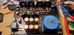
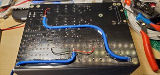
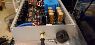
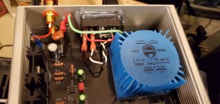
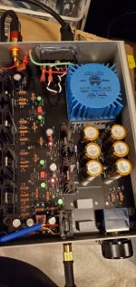
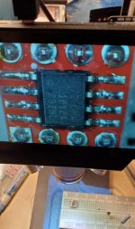
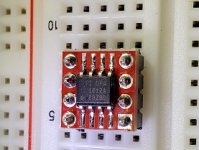
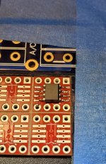

Thanks to Jim (6L6) for the great build guide and parts list!

Not that it matters even the slightest bit when the lid is on, I didn't like the way the input and output wires crossed back and forth so I decided to run mine under the board. I considered drilling a hole in the big empty space at the back for output but couldn't decide if I was going to try and fit a big fat switched/filtered/fused Schaffner power inlet module and went with the $ friendly option at the end. Instead of drilling through the middle of the board - because I couldn't see any traces/tracks due to the black silk screen (can't see throught it), I decided to just drill through the mounting hole instead. One in the front for the output and then one in the back. It made connecting the inputs a bit tricky but not a big problem.
On the front, I ordered a black Neutrik locking connector but again, decided to go with the $ friendly option but mostly because I didn't like the idea of trying to drill an almost 1 inch hole in such a thin faceplate.
I've got 3 or 4 (5?) other headamp builds in mind so I'll save the nicer parts for one of those.
I installed a vintage LM4562 to begin with and found it to sound a bit brittle right out of the gate, which smoothed out over the next hour of listening. A great test is Norah Jones - "Don't Know Why" at 1:13 - there is audible clipping in the recording that I hear in all revealing systems. This is an acid test of course, not to say it sounded bad at all. It was very enjoyable but it was very late so I packed it in and got the itch to attempt my first SMD soldering - OPA1612 into Sparkfun SOIC-8 to DIP-8 adapter from Digikey (4.50 for 4 pcs). I finally got the chance to use the Aliexpress LCD microscope, which performed great!
I am enjoying the OPA1612 and being completely unfair to the LM4562 in that I'm letting it burn in now before further evaluation but found it very enjoyable (much more so than the LM4562) but will come back and try it again after I get used to the 1612.
Anyway, TLDR right? Everybody just comes for the pictures so I won't keep you waiting any longer. Enjoy!
Oh, right - because someone will ask - I tried HE400i, Grado SR80 and AKG Q701. I like the sound of the AKG the most but the bumps make my head hurt rather quickly so the HE400i is my favorite ... although I was burning it in with the Grado SR80 and am enjoying it very much as I type this 😀 (Listening to Billie Eilish - Just No Time To Die).


Routing the wires underneath... I love it!!! 
Looks really good, well done!
Enjoy the music. 🙂 🙂 🙂

Looks really good, well done!
Enjoy the music. 🙂 🙂 🙂
... and yes, I did the old 'measure once and cut way too much' with the inlet cutout. Glue gun to the rescue! Barely visible from the outside.
Next builds in the line:
Elekit TU-882R (thanks Victor!)
F4 HA boards that I built 12 years ago (time to go into a case)
Aleph Mini (BrianGT black boards) Aleph-H build, convert to a AJ-H (AJ-H?) and substitute Cree VFETs
... I'm sure something else will come up
Never completed a headamp before so let me know if this is good, great or just ok. Offset is stupid compared to what I'm used to - 0.5mW and 0.6mW. Measured with pokey pokey probes instead of hooks but I can measure for real if I should.
Last edited:
Very nice build !
I keep thinking that whammy board was made with the bigger side for the front (where the transistors are placed)
But when I see the pot placement it gets me confused 🙂
Enjoy the music
I keep thinking that whammy board was made with the bigger side for the front (where the transistors are placed)
But when I see the pot placement it gets me confused 🙂
Enjoy the music
Congrats twitchie on your build. I've been through 8 different opamps and keep coming back to the OPA1612 as the one that sounds consistently the best no matter which type of headphone I throw at it, open dynamic, closed dynamic or planar.
I got the single rail board built and up and running. It works sweet and would be a good PSU for anyone that just needs a positive supply that's dead quiet. I need 2 of these boards for testing so I got 8 boards left. 🙂
This looks fantastic. I'd love to check out some of those boards. Please ping me offline.
Question: have you put this into one of the typical chassis used for the WHAMMY ? The Hammond one surely would not accommodate this, and I think the Galaxy 2U I used would barely fit this if I put the main board right up against one side. I am wondering if a narrower version could be made, perhaps with a smaller transformer, or having it mounted perpendicular to the board or something but then my concern would be about the radiated fields affecting the I/O ports on the back.
Perhaps a better solution is to do an external PSU with 4 wires coming out of it: 2 for the main board power, 2 for the LED surrounded by a shield?
Two of these boards fits very easily in the standard Hammond enclosure as I am making a power supply with 2 boards that supply 5v and 24v. The boards are smaller than they look in the pics. 🙂
Two of these boards fits very easily in the standard Hammond enclosure as I am making a power supply with 2 boards that supply 5v and 24v. The boards are smaller than they look in the pics. 🙂
Thats where I was going: two PSUs in an external box!
I'd be a glad and willing guinnea pig for this external PSU prototyping exercise. 🙂
--Tom
Very helpful guide. I would like to install an led on the front panel but do not want to divert D5 or D6. You suggest a better alternative would be connecting an LED to the V+ and ground of the raw PSU. Where is the best place to do this (underside of circuit board)? and what value of resistor would you advise. If I do this is the wiring route to the front panel important to avoid induced hum. Many thanks
I was going to do exactly this and have a hole drilled just above the volume knob in the front panel of my build a few posts back.
My plan is to tap it off the raw rectified output before the first bank of smoothing caps as I don't care if the LED sees noise and any noise the LED contributes will get filtered out by the smoothing caps and regulator.
We'll see if the LED likes 35V. I plan on using a nice blue LED
I am going to run mine along the side of the case on the PSU side up to the attenuator.
My plan is to tap it off the raw rectified output before the first bank of smoothing caps as I don't care if the LED sees noise and any noise the LED contributes will get filtered out by the smoothing caps and regulator.
We'll see if the LED likes 35V. I plan on using a nice blue LED

I am going to run mine along the side of the case on the PSU side up to the attenuator.
I was going to do exactly this and have a hole drilled just above the volume knob in the front panel of my build a few posts back.
My plan is to tap it off the raw rectified output before the first bank of smoothing caps as I don't care if the LED sees noise and any noise the LED contributes will get filtered out by the smoothing caps and regulator.
We'll see if the LED likes 35V. I plan on using a nice blue LED
I am going to run mine along the side of the case on the PSU side up to the attenuator.
I don't think the LED will like 35vdc but you can compute the proper voltage drop and stick a resistor in front of it. 🙂
pfarrell has an led installed. People seem to be tapping it off the regulated side. I don't think it should be the end of the world but in my case I hear that blue LEDs are noisy and it's probably negligible load but I'd rather not have any voltage drop introduced if I can avoid it.
pfarrell's build
pfarrell's build
pfarrell has an led installed. People seem to be tapping it off the regulated side. I don't think it should be the end of the world but in my case I hear that blue LEDs are noisy and it's probably negligible load but I'd rather not have any voltage drop introduced if I can avoid it.
pfarrell's build
Same here. I've not measured the noise diffs, but this is a common piece of advice all across many of the DIYaudio forums, so I've avoided Blue LEDs tapped off any non-LED dedicated rails myself, and also why Ive been pondering how to setup a separate tap for the LED on the WHAMMY.
Blue LED are noisy when used as a voltage reference, not as a light bulb. 🙂
Just take power off the PSU from V+ to ground somewhere, it’s not critical.
Just take power off the PSU from V+ to ground somewhere, it’s not critical.
Blue LED are noisy when used as a voltage reference, not as a light bulb. 🙂
Just take power off the PSU from V+ to ground somewhere, it’s not critical.
Thats a relief. I've been fretting about how to get a separate v+ in there.
Thanks again for level setting things 6L6!
- Home
- Amplifiers
- Pass Labs
- "WHAMMY" Pass DIY headphone amp guide