Jim:
PM sent. Would love two kits, if they're available, but will be happy to take the last one if that's all that's left.
Regards,
Scott
PM sent. Would love two kits, if they're available, but will be happy to take the last one if that's all that's left.
Regards,
Scott
The most frequently asked questions about the schematic in post #1, at least the ones that I've heard most, seem to be
Have fun with them!
1. There's an RC network on the base of Q7, why not have the same network on the base of its mirror image transistor, Q11?
2. Where in the circuit might we install a few capacitors, to get lower distortion and/or better PSRR?
3. If I were to hand-match pairs of bipolar transistors for this circuit, which ones would give the greatest benefit?
2. Where in the circuit might we install a few capacitors, to get lower distortion and/or better PSRR?
3. If I were to hand-match pairs of bipolar transistors for this circuit, which ones would give the greatest benefit?
Have fun with them!
#1 because it made it work and closed loop you can't tell plus it is less parts.
But I may be wrong.
But I may be wrong.
#1 because it made it work and closed loop you can't tell plus it is less parts.
When the designer says "I made decision D because of reasons X, Y, and Z" that's about as definitive as it will ever get.

PARTS KIT UPDATE -
1) I have received many PM, thank you for the interest!
2) I have not responded to any of you via PM yet, so don't worry if it's been quiet.
3) I'm waiting to receive the rest of the pink PCBs from Wayne. Nothing will happen on my end until I have them.
4) As of this time the list is full.
If you are still interested, please send another PM with -
User Name, Real name, post address and best email.
And all forthcoming correspondence will be via Email.
Thanks!
Jim
I have received the second message from the following -
Dudeisms
chat72
takitaj
Russellc
Mod Man
Jamayfie
phomchick
BDP
wdecho
DRoche
Damuffin
Robert8
andreasw
Mordkai
Rickcl
drpro
Gricko
Chul
bologna1
Arthur
Dane
gary s
Perj
Adason
SRMcGee
Dennis Hui
rookakoma
jwjarch
NihonJR06
kbergsson
MEPER
If you are not listed here and are still wanting a parts kit, please read post #67 again. 😀
Thanks
Last edited:
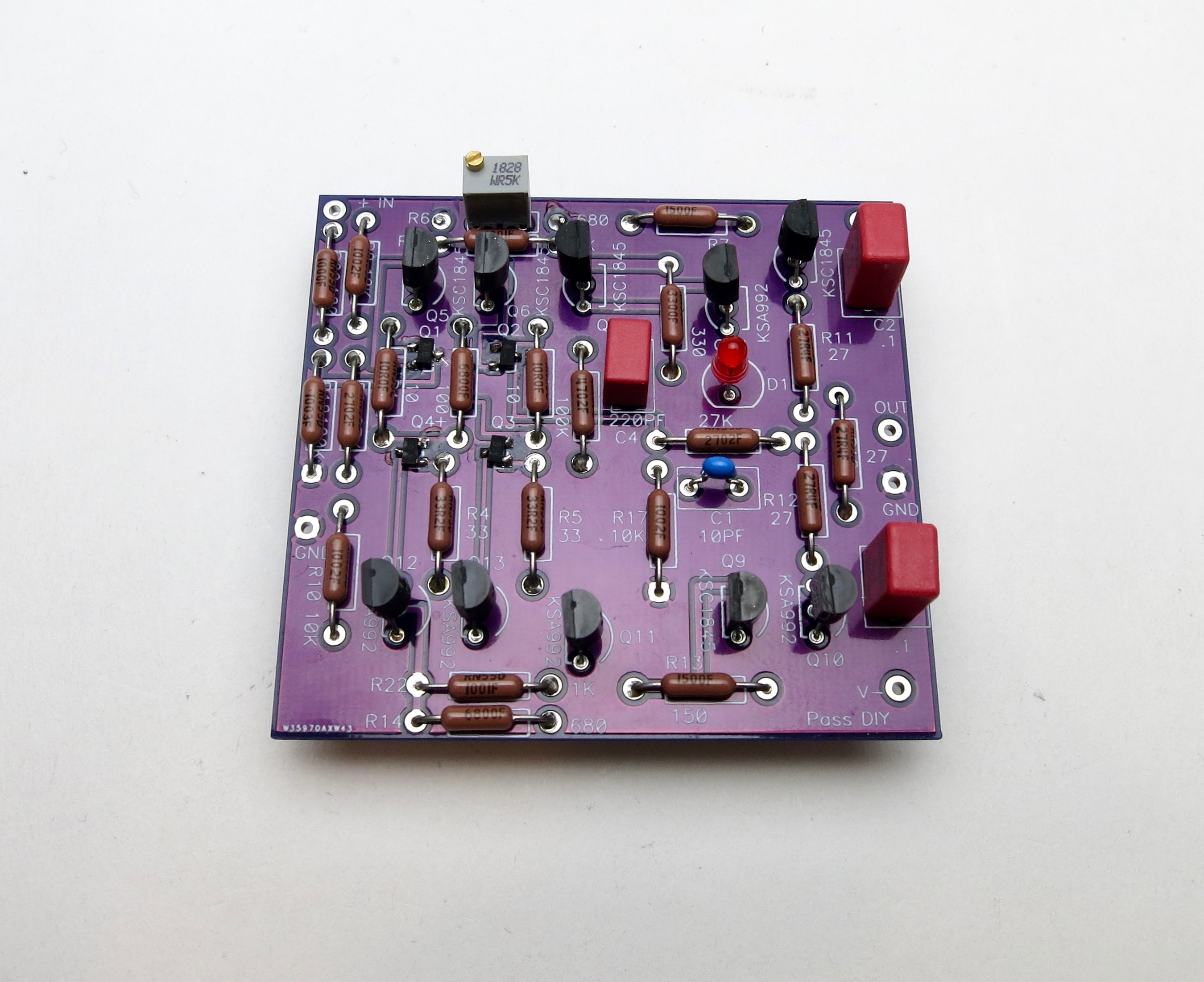
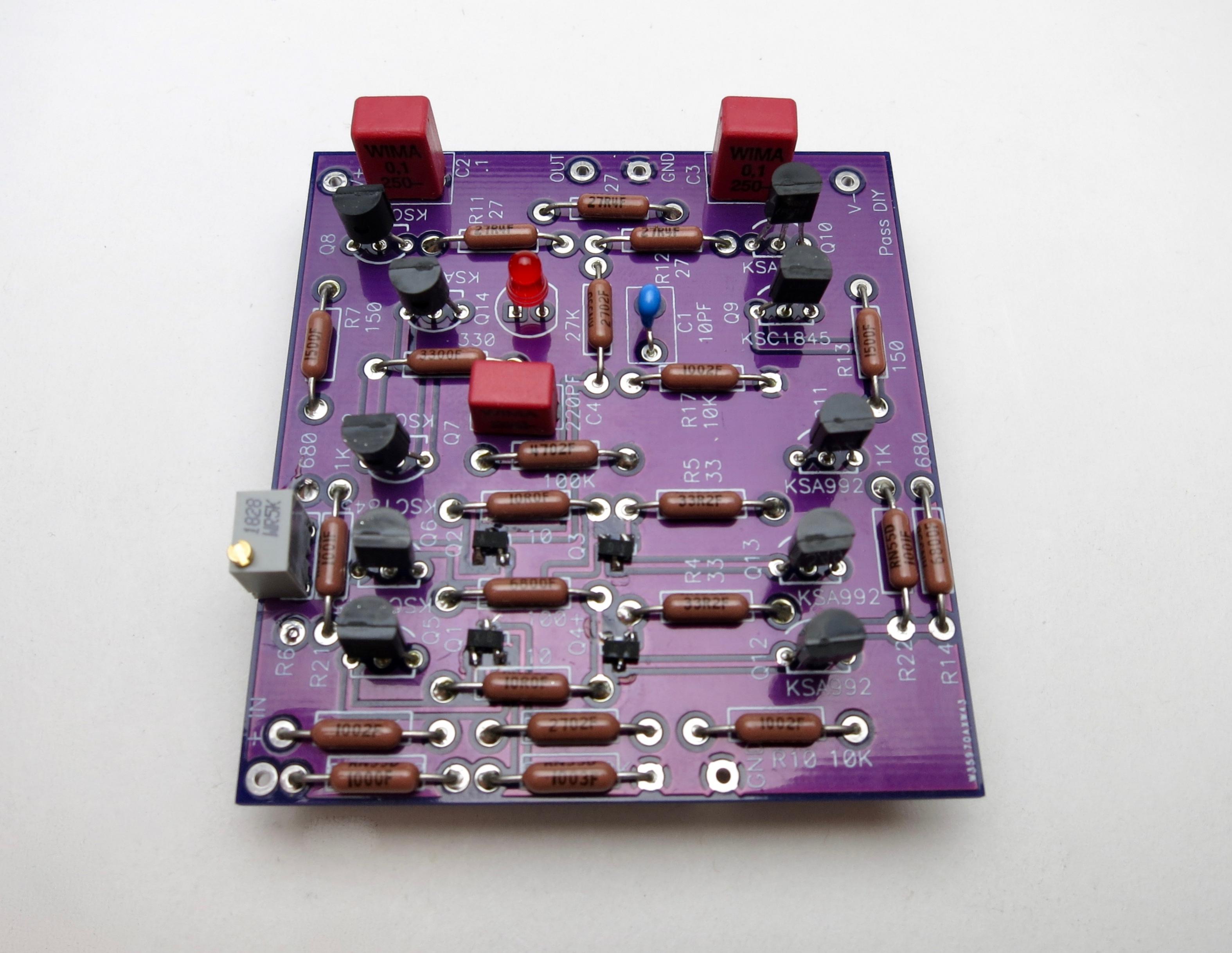
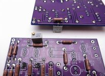
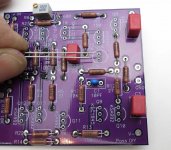
Parts in the kit will stuff the PCBs as shown -


Stuffing order is SMD jfets first, followed by the resistors.
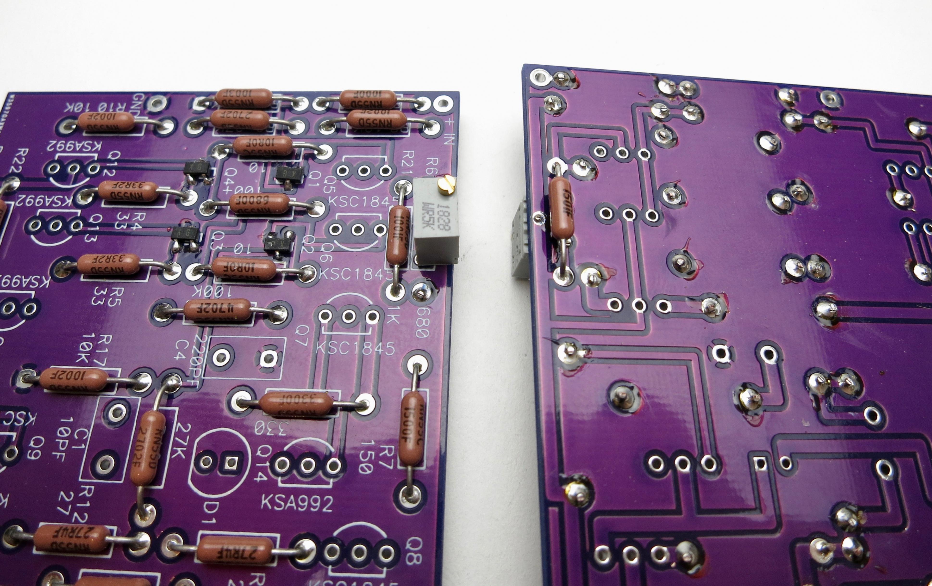
NOTE - R6 attached to the bottom of the PCB, it's also marked 68- but 1.5k is on the schematic and that's supplied.
Attach ONLY after the pot is soldered. 🙂


LED has no notched side, so long leg into the square pad
Stuffing order is SMD jfets first, followed by the resistors.
NOTE - R6 attached to the bottom of the PCB, it's also marked 68- but 1.5k is on the schematic and that's supplied.
Attach ONLY after the pot is soldered. 🙂
LED has no notched side, so long leg into the square pad
Attachments


Last edited:
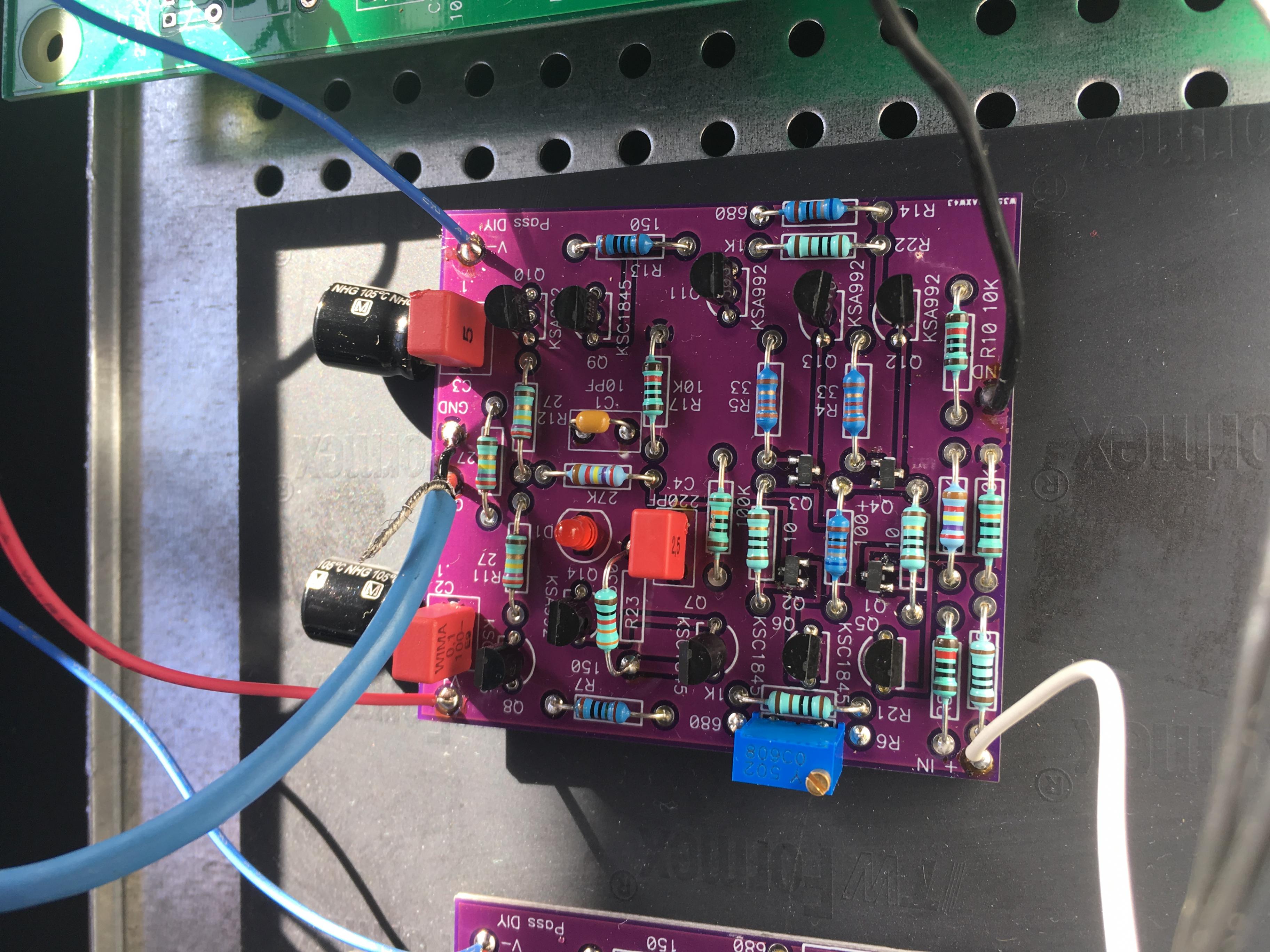
This may just be a dumb newbie question, but at Burning Amp Wayne had two extra caps at C2 and C3 in addition to the red square caps... do we need those as well?
You are referring to the 220uF electrolytic cans soldered in parallel with the film caps on the bottom of the board... The short answer is no;
Wayne added those because in that particular build he also added some series filter resistors feeding the PCB from the Power Supply - with that extra R filter, (which ended up being not necessary) the bigger caps downstream help keep the PSU sagging if there's a big transient. With no series resistance the film caps on the top of the PCB are more than sufficient fo the job, and the bigger cap is superfluous because the preamp board has direct access to the regulator's output with nothing in the way.
Look at the other photo from that post and you'll see those resistors the amp boards are connected to.
List of people who have contacted me the 2nd time in post #68 has been updated.
I'm waiting for the PCB to arrive from Wayne, and I have to go work for a few days, when I have everything ready to go I'll contact you each via email.
I'm waiting for the PCB to arrive from Wayne, and I have to go work for a few days, when I have everything ready to go I'll contact you each via email.
P1 pot adjusts what, dc offset?
With R16 and R17 both stuffed and soldered, DC offset is established at [Q1234_mismatch * (R16+R17)/R17)] and is not much affected by P1.
Instead, P1 adjusts the strength of the pushers versus the strength of the pullers. Perfection occurs when they are exactly equal strength. This minimizes distortion.
One way to make the adjustment is to proceed with R16 removed from the circuit (temporarily: R16 = Infinity). Then monitor the voltage across R6 while sloooooowly dialling P1. When the voltage across R6 exactly equals the voltage across R14, stop. You could get confirmation by verifying that the voltage across R7 exactly equals the voltage across R13.
All the above is 100% accurate, and it's also measured by adjusting the DC offset on the output to zero.
Last edited:
All the above is 100% accurate, and it's also measured by adjusting the CD offset on the output to zero.
Is the way Wayne explained the adjustment the way you adjusted P1?
Thanks for the quick answer guys. I did not see where Wayne explained the P1 function or adjustment in his presentation. Or I just missed it.
I guess an alternative view is that P1 allows you to add or subtract a small DeltaV to the output of the first stage. Since the first stage's output equals Vin*gm, changing its output by DeltaV is equivalent to changing its input by (DeltaV / gm). Voila, a way to inject an offset at the first stage input. Which is the input to the amplifier as a whole.
The amplifier's output is Vin*(R16+R17)/R17 so the effect of DeltaV at the first stage, thanks to dialling P1, becomes
* ChangeAtAmplifierOutput = (DeltaV / gm) * (R16+R17)/R17
So you could use P1 to eliminate input offset / output offset, if you wished. However this might result in increased mismatch between pullers and pushers.
I guess an alternative view is that P1 allows you to add or subtract a small DeltaV to the output of the first stage. Since the first stage's output equals Vin*gm, changing its output by DeltaV is equivalent to changing its input by (DeltaV / gm). Voila, a way to inject an offset at the first stage input. Which is the input to the amplifier as a whole.
The amplifier's output is Vin*(R16+R17)/R17 so the effect of DeltaV at the first stage, thanks to dialling P1, becomes
* ChangeAtAmplifierOutput = (DeltaV / gm) * (R16+R17)/R17
So you could use P1 to eliminate input offset / output offset, if you wished. However this might result in increased mismatch between pullers and pushers.
Thanks Mark. When I get the kit I will adjust the way you described.
- Home
- Amplifiers
- Pass Labs
- Wayne's BA 2018 linestage