I‘m convinced that it is not that complicated. Wayne was talking about the purple boards, those we’re working with got things changed (this is how I understand 6L6)
And I believe he did the same on his ba-3 but reversed the decision...
I think we're not understanding each other. What I mean to say is that CN2/3 is connected to R17 by a trace (verified with multimeter). But the schematic omits the connection for clarity and uses a pair of [-IN] symbols to represent the hidden connection. They can be interpreted as:

So you should only be hooking up to the screw terminals at the edges -- nothing connects at the middle of the board.
Last edited:

I was confused by Wayne's response (post 263) but finally realized he was referring to the first batch of boards that did not have a -IN. For the most recent boards, Jim (6L6) is correct, as always: I jumpered the two inputs (GND and -IN) together for SE operation. Just finished it and my cheapo test speakers have never, ever, sounded so good. Giant THANKS to Wayne and Jim, and Jason at diyAudioStore. Also, thanks again to Mark Johnson for the VRDN power supply. What a fantastic and satisfying project!
I know, it doesn't really exist if I don't post a picture, so I'll have to figure out how to do that.
I know, it doesn't really exist if I don't post a picture, so I'll have to figure out how to do that.
Wayne, 6L6, all in this forum:
Many thanks already.
It feels so cool to have self-built, highly praised device in front of me.
I‘m not yet able to lend it my ear, but I’m close!
Connect inputs is next, then ... the serious dream begin (making decisions about final Lay-out, chassis/knobs etc...)
Already happy!


Many thanks already.
It feels so cool to have self-built, highly praised device in front of me.
I‘m not yet able to lend it my ear, but I’m close!
Connect inputs is next, then ... the serious dream begin (making decisions about final Lay-out, chassis/knobs etc...)
Already happy!
Did what on the BA-3?
... did connect it „that“ way...
https://www.diyaudio.com/archive/gallery/data/500/IMG_2265.jpg
That’s comparing apples to oranges. The BA-3 front end as shown in that guide is only SE in SE out.
Another WCLS18 is alive. Sounding great so far. Coming from my BA3 pre, this LS really adds more detail and oomph to the bottom end. Really awesome linestage! As far as the build goes, I have a 2U chassis with an attenuator and a Salas UltraBIB. Makes it really easy to swap in different boards and adjust the voltage as needed. The bottom plate looks like Swiss cheese 😀
Attachments

apples to oranges.
I was speculating on something like that. Should have refrained on commenting...

to myleftear #1625
Hello myleftear,
very good values! Very low offset. All looking good so far.
Greets
Dirk
Hello myleftear,
very good values! Very low offset. All looking good so far.
Greets
Dirk
Hello myleftear,
very good values! Very low offset. All looking good so far.
Greets
Dirk
Thank you Dirk!
Adjusting the offset in these small scales is a bit like balancing a house of cards [emoji23]
It often changed some mV just by moving the cable... (I had it at zero for a mere few seconds)
Wayne, 6L6, all in this forum:
Many thanks already.
It feels so cool to have self-built, highly praised device in front of me.
I‘m not yet able to lend it my ear, but I’m close!
Connect inputs is next, then ... the serious dream begin (making decisions about final Lay-out, chassis/knobs etc...)
Already happy!
View attachment 872507
View attachment 872508
View attachment 872509
View attachment 872510
I'm getting started on adjusting mine and came here looking for info. I was surprised to see your photos from earlier that looked like you were measuring bias at the inputs:
I have been measuring bias at GND and OUT on the other side of the board:

Which to be honest isn't giving me what I was expecting for initial values...
Last edited:
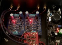
I am starting to do some measuring/adjusting P1 on my board. My VRDNs are both putting out exactly +/-18V which is a good starting point.
Before going any further (e.g. removing R16 to set P1) thought I'd measure the bias as-is. I was surprised to see about 590mV on both channels (1st photo). Then I remembered on the F5 it was recommended to short the signal inputs, so I (probably wrongly) connected +IN, GND and -IN on the input side. This ended up making the bias 2V on both channels (2nd photo). Same result if I only shorted -IN to GND and left IN+ floating. So that wasn't the issue, and clearly isn't helping (or correct?).
Am I correct in measuring the bias as shown? Note that since I'm not using a chassis yet (unless you count bolting everything to cardboard) I haven't connected the IEC ground to anything, and haven't set up a floating ground between IEC/chassis and the signal ground.
Any tips before I proceed? I will eventually remove R16 and compare R6/R14 while adjusting P1 as recommended, but I want to make sure I'm measuring and set up correctly. I read that P1 doesn't have much effect when R16 is present so I doubt playing with it would correct my 590mV bias.
Floating inputs:
Shorted inputs:

Wiring overview.

Note the probes were swapped in all the photos, so displays showed negative biases.
Before going any further (e.g. removing R16 to set P1) thought I'd measure the bias as-is. I was surprised to see about 590mV on both channels (1st photo). Then I remembered on the F5 it was recommended to short the signal inputs, so I (probably wrongly) connected +IN, GND and -IN on the input side. This ended up making the bias 2V on both channels (2nd photo). Same result if I only shorted -IN to GND and left IN+ floating. So that wasn't the issue, and clearly isn't helping (or correct?).
Am I correct in measuring the bias as shown? Note that since I'm not using a chassis yet (unless you count bolting everything to cardboard) I haven't connected the IEC ground to anything, and haven't set up a floating ground between IEC/chassis and the signal ground.
Any tips before I proceed? I will eventually remove R16 and compare R6/R14 while adjusting P1 as recommended, but I want to make sure I'm measuring and set up correctly. I read that P1 doesn't have much effect when R16 is present so I doubt playing with it would correct my 590mV bias.
Floating inputs:
Shorted inputs:
Wiring overview.
Note the probes were swapped in all the photos, so displays showed negative biases.
Last edited:
I swapped the multimeter leads (they were reversed above) to get a better photos, and only had -IN shorted to GND with +IN floating. Plugged it in and both fuses blew at the same time.
So something's clearly off... BTW, I ordered T 80mA (slow blow) fuses based on my calculation (15VA/230V ~= 65mA). Should these be sufficient assuming normal operation? I've got 8 more thankfully...
So something's clearly off... BTW, I ordered T 80mA (slow blow) fuses based on my calculation (15VA/230V ~= 65mA). Should these be sufficient assuming normal operation? I've got 8 more thankfully...
Last edited:
Do you mean bias (Iq) or DC offset? Looks like you’re measuring for offset.
Sorry, yeah I meant offset. Darn, it's too late to fix my original post.
Last edited:
- Home
- Amplifiers
- Pass Labs
- Wayne's BA 2018 linestage