WLS - I put it into cases
Hello members,
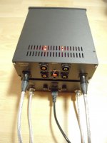
I put my Waynes-BAF2018-Linestage and the PSU into cases.
Dual-Mono in two cases. Each channel has its own PSU.
You will ask: 'Where is the volume pot and input selector?'
Answer: 'In another (third) case...'😀
Greets
Dirk
Hello members,
I put my Waynes-BAF2018-Linestage and the PSU into cases.
Dual-Mono in two cases. Each channel has its own PSU.
You will ask: 'Where is the volume pot and input selector?'
Answer: 'In another (third) case...'😀
Greets
Dirk
Attachments


You achieve pretty good results by using the Allo Boss in conjunction with their isolator board. The isolator sits between the Pi and the DAC, allowing you to have complete galvanic isolation. You'll need separate supplies, obviously. I built one of these a few years ago and powered the DAC from LiPo batteries. It is completely free from Pi "noise". The player runs piCorePlayer software.
See this post in the Logitech Squeezebox forum for the example I built: pi based systems - Page 6
There are other builds in that thread too.
OK, let's start by not discussing matters I know little about, like how that galvanic isolation between the DAC and the Pi happens. I would love having more information about it, even if my present setup did work fine for some time, using the Topping D50 as DAC, through USB. So mine or yours seem to work.
What I did love in your system was that screen you put up front with the VU meters, which seems to have some play control that resembles an actual player, which I missed on the simple remote I was using. You know: play, pause, stop, rewind, fast-forward. I miss that on my Nvidia Shield and on regular TV Android boxes.
The reason I picked picoreplayer was because it seems to be the only one that doesn't rely on a cell phone for remote controlling, which I definitely do now want.
I will need to get back to it all, and assemble the system again, this time with Windows 10. I'm slowly moving from Windows 7 to 10, and I had some issues that now more or less seem to be solved.
Now, what did the Wayne's preamp add to your system in audio quality?
What power amplification are you using?
The other path you described, with AMB system, seemed another thing I might be interested in. If I could adapt it to be used as a 5.1 or 7.1 HT preamp. Do you think it's possible?
Obstacle ahead: wanted to do the input connection, but single ended...
I think it is just as Wayne explained (#263, https://www.diyaudio.com/forums/pass-labs/329240-waynes-ba-2018-linestage-27.html#post5699074 ), but this surpasses me—R17 being deep inside the pcb, am I really supposed to feed the minus in there?
No shortcuts (connect ground to both in- and gnd or something)?
Thank you!
Idea brewing...
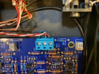
The blue board is actually two individual circuits on 1 pcb, right? So, if done properly, the channels could be physically separated, yes? (I fear this goes a bit into blasphemics, but, me thinking freely...
The blue board is actually two individual circuits on 1 pcb, right? So, if done properly, the channels could be physically separated, yes? (I fear this goes a bit into blasphemics, but, me thinking freely...
LeftEar - are you connecting a Single-ended input or a balanced input?
Yes, I suppose if you really wanted to you could cut the PCB in half. That said, the current PCB is already electrically separates channel to channel. So there’s no real benefit.
Yes, I suppose if you really wanted to you could cut the PCB in half. That said, the current PCB is already electrically separates channel to channel. So there’s no real benefit.
Have some fun and take some risk! Score the PCB with a utility knife but don't cut it all the way through. Then tape the board to a tabletop or countertop, such that half of the PCB and the score-line are hanging over the edge, out in the free air. When it's in position, give the board a swift karate-chop to break the board right at the score line. And enjoy yourself! It's a hobby, it's supposed to be fun.
Have some fun and take some risk! Score the PCB with a utility knife but don't cut it all the way through. Then tape the board to a tabletop or countertop, such that half of the PCB and the score-line are hanging over the edge, out in the free air. When it's in position, give the board a swift karate-chop to break the board right at the score line. And enjoy yourself! It's a hobby, it's supposed to be fun.
Thank you mark!
Ergebnis der Google-Bildersuche
Might want to look at a spot to place mounting holes, I didn't see any space to put mounting holes in the center, near the score line.
myleftear
Will this help? Here's my working preamp (in my rudimentary test bed amplifier chassis). Hope you can follow the wiring (it is single ended). I included a wiring diagram too just in case. You can see the inputs (RCA's out of the chassis) and output (installed on the chassis). Offset was about 0.4mV.


Will this help? Here's my working preamp (in my rudimentary test bed amplifier chassis). Hope you can follow the wiring (it is single ended). I included a wiring diagram too just in case. You can see the inputs (RCA's out of the chassis) and output (installed on the chassis). Offset was about 0.4mV.
Might want to look at a spot to place mounting holes, I didn't see any space to put mounting holes in the center, near the score line.
Nope, would have to improvise—something similar to how the purple boards were mounted...
follow the wiring (it is single ended). I included a wiring diagram too just in case...
Oh yes, this clears it, especially the diagram!
Thank you!
... Single-ended input or a balanced input?
Sorry to bug you again (connection-method seems to be cleared), but could you explain what exactly Wayne was about in the aforementioned post (#263, in this thread) of him?
Obstacle ahead: wanted to do the input connection, but single ended...
I think it is just as Wayne explained (#263, https://www.diyaudio.com/forums/pass-labs/329240-waynes-ba-2018-linestage-27.html#post5699074 ), but this surpasses me—R17 being deep inside the pcb, am I really supposed to feed the minus in there?
If I understand correctly, CN3 connects to one side of R17. The [IN-] boxes on the schematic are connected to each other, but the line isn't drawn between them because it would cross a lot of other lines and make the schematic more cluttered. This notation is similar to how a schematic may show multiple unconnected ground symbols to make it more readable when connecting them all with lines would make a mess.
Of course I could have totally misunderstood the question. 🙂
Ahhh,I see. Noted. Thank you 6L6!Don't attach the input -IN to PSU GND. Merely make a small jumper to attach - IN to input GND. (CN2 and CN4)
If I understand correctly, CN3 connects to one side of R17.
I‘m convinced that it is not that complicated. Wayne was talking about the purple boards, those we’re working with got things changed (this is how I understand 6L6)
And I believe he did the same on his ba-3 but reversed the decision...
- Home
- Amplifiers
- Pass Labs
- Wayne's BA 2018 linestage