How constant is the DC offset supposed to be? Mine is dancing around constantly and swinging between + and - 500mV. For the large outputs it seems low powered too. I tested with headphones, then DIY F6 and output seems low and lacking bass. It's clean sounding and quiet, no hum or noise, but volume has to be over half way. I suspect something's not quite right. I used the pmillett PS suggested and have it at 18.5V + and - solid.
How constant is the DC offset supposed to be? Mine is dancing around constantly and swinging between + and - 500mV. For the large outputs it seems low powered too. I tested with headphones, then DIY F6 and output seems low and lacking bass. It's clean sounding and quiet, no hum or noise, but volume has to be over half way. I suspect something's not quite right. I used the pmillett PS suggested and have it at 18.5V + and - solid.
Mine drifts around between +/-5mV with the board out in the open. So +/-500mV seems high. Unfortunately I don't know enough to offer any advice.
Stinkpot - As always, please post a series of well-lit, in-focus photos. Do this first.
Something is not right, most likely a missed solder connection somewhere. That’s a lot of dancing on the output.
The big output transistors increase the current capability, not the gain. Gain is about 3.6x with the stock feedback resistor. Don’t confuse where the volume knob needs to twist with gain.
I had an offset problem with one channel that was caused by flux residue
around one of the jfets. Cleaning that fixed my problem. So perhaps you might
have a look at that, in addition to the other soldering.
The gain, as Jim mentioned, is 3.6x. That may be less than what you are used to
and you just need to turn the volume knob higher.
around one of the jfets. Cleaning that fixed my problem. So perhaps you might
have a look at that, in addition to the other soldering.
The gain, as Jim mentioned, is 3.6x. That may be less than what you are used to
and you just need to turn the volume knob higher.
Fantastic Linestage
Just finished my build and I'm delighted! Excellent resolution, detail and extension, yet no glare or hardness. Very addicting sound signature (or lack thereof). Will spend some time in the next few days going though my music collection.
Thanks to Wayne for sharing his design and thanks to the diyAudio crew for creating the kit.
Attachments
Outstanding Workmanship
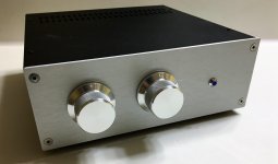
Wkcox you guys are killing me with those nice cases. I guess it is time for me to get me one of those. What kind of "selector" switch is that you have. Kind of looks like a "Glass-Ware"
You can view my "Case" in post 1585!!!😀😀
Mine Goes to 11
Wkcox you guys are killing me with those nice cases. I guess it is time for me to get me one of those. What kind of "selector" switch is that you have. Kind of looks like a "Glass-Ware"
You can view my "Case" in post 1585!!!😀😀
Mine Goes to 11
Last edited:

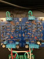
Check R8, R10 and R24, R34 just to be sure my eyes aren't playing tricks against the schematic and values.
Edited - Check R1 and R27 too. Essentially, check all 10Rs against all 10ks.
Edited - Check R1 and R27 too. Essentially, check all 10Rs against all 10ks.
Last edited:
You’ve got 10ohm where the 10K go and vise-versa.
10R0 is 10.0 ohms
1002 is 100+two zeroes, I.E., 10K
10R0 is 10.0 ohms
1002 is 100+two zeroes, I.E., 10K
Last edited:
Absolutely fantastic!! Looks superb, well done!
Thanks Jim. Your encouragement and continued support of this site is awesome!
Wkcox you guys are killing me with those nice cases. I guess it is time for me to get me one of those. What kind of "selector" switch is that you have. Kind of looks like a "Glass-Ware"
You can view my "Case" in post 1585!!!😀😀
Mine Goes to 11
Your case is biodegradable and goes to 11. What more could you ask for?
Yes, the selector is a GlassWare Select-2, which selects from 3 inputs. Their Select-5, which I also have, selects from 4 inputs. Great switches and but confusing naming convention!
I highly recommend the HiFi 2000 cases from the diyAudio store. They're very high quality and an excellent value.
@WHCox
When I see long runs of nice twisted pair wiring from back to front of preamp enclosures I wonder if the switches shouldn't be located at the back and actuated via long front-to-back shafts. Wouldn't that be quieter (if less colourful)?
Or is the cost/benefit unfavourable?
When I see long runs of nice twisted pair wiring from back to front of preamp enclosures I wonder if the switches shouldn't be located at the back and actuated via long front-to-back shafts. Wouldn't that be quieter (if less colourful)?
Or is the cost/benefit unfavourable?
No transformers, switching power supplies, or 120 VAC in the case so little potential for interference or noise pickup. Absolutely no hum or any unwanted artifacts at max volume in my system or on the test bench. It’s been my preference to keep transformers out of the case when building preamps for best performance without the need for shielding.
hi Jim(6L6),
Sorry for my ignorance. I got the early pre production purple board a while ago after Wayne presented his design at the BAF. I just finished ordering all the parts and about to start on the project.
Besides, the new mounting hole, input/output connector changes in the new BLUE production release, are there any design/component changes in the latest production blue board vs the early purple version that Wayne gave out at the BAF amp camp ?
Thanks,
TD
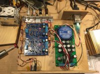
Up & running
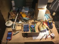
Up and running on the first attempt this evening. I am so happy. Now to add an I_Select board and sort out a proper chassis. Many thanks to 6L6 and this forum for getting me this far.
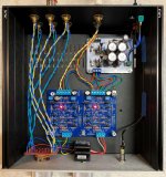
The input lines from the RCA to the Pot and back to the PCB are long and are acting a bit like an antennae and inject a tiny bit of 30 hz hum (more when I but my hand near them or touch them). I added a ground wire between the pot faceplate mounting shaft and the RCA jack ground plane (that little piece of right angle aluminum) and that knocked most of it out. In the final application, the power supply will be in another enclosure, the pot will be at the back (on an I_Selet board), the wire lengths will be far shorter and there will be a better grounding scheme with a metal enclosure which I expect will remedy the problem. Any comments or guidance on this topic are appreciated.
On the power supply (Pete Millet Design) the voltage from Ground to V+ is 15.5V and the voltage from Ground to V- is 14.7V. Is this normal variation? Do I have problem on the power supply board? Will this even have an effect the BA2018 linestage performance?
Thanks and be well.
Up and running on the first attempt this evening. I am so happy. Now to add an I_Select board and sort out a proper chassis. Many thanks to 6L6 and this forum for getting me this far.
The input lines from the RCA to the Pot and back to the PCB are long and are acting a bit like an antennae and inject a tiny bit of 30 hz hum (more when I but my hand near them or touch them). I added a ground wire between the pot faceplate mounting shaft and the RCA jack ground plane (that little piece of right angle aluminum) and that knocked most of it out. In the final application, the power supply will be in another enclosure, the pot will be at the back (on an I_Selet board), the wire lengths will be far shorter and there will be a better grounding scheme with a metal enclosure which I expect will remedy the problem. Any comments or guidance on this topic are appreciated.
On the power supply (Pete Millet Design) the voltage from Ground to V+ is 15.5V and the voltage from Ground to V- is 14.7V. Is this normal variation? Do I have problem on the power supply board? Will this even have an effect the BA2018 linestage performance?
Thanks and be well.
Attachments
Up and running on the first attempt this evening. I am so happy. Now to add an I_Select board and sort out a proper chassis. Many thanks to 6L6 and this forum for getting me this far.
The input lines from the RCA to the Pot and back to the PCB are long and are acting a bit like an antennae and inject a tiny bit of 30 hz hum (more when I but my hand near them or touch them). I added a ground wire between the pot faceplate mounting shaft and the RCA jack ground plane (that little piece of right angle aluminum) and that knocked most of it out. In the final application, the power supply will be in another enclosure, the pot will be at the back (on an I_Selet board), the wire lengths will be far shorter and there will be a better grounding scheme with a metal enclosure which I expect will remedy the problem. Any comments or guidance on this topic are appreciated.
On the power supply (Pete Millet Design) the voltage from Ground to V+ is 15.5V and the voltage from Ground to V- is 14.7V. Is this normal variation? Do I have problem on the power supply board? Will this even have an effect the BA2018 linestage performance?
Thanks and be well.
You should have used one of my PSU boards. It uses the same regulators as Pete's but mine has adjustable output voltage so you can match the output for both the positive and negative exactly.
On Pete's PSU don't worry about the voltage variation it happens with regulators they will hardly ever equal each other so it's quite normal. Hope this helps.
Looking good!
Rail voltage difference won't make any effect on the operation. The two regulators have very slightly different internal reference voltages, so of you want to get the output voltages matched, you need to put pots in place of R4 and R6. (20K, tie one leg to the wiper and use them as variable resistors)
Talking abut layout noise is kind of a moot point when you are not in a metal chassis, when you are in metal we can discuss.
Having the PSU in an outboard enclosure isn't necessary, it can be quiet all in one box. Save the outboard PSU for a phono stage where it genuinely makes a difference.
On the power supply (Pete Millet Design) the voltage from Ground to V+ is 15.5V and the voltage from Ground to V- is 14.7V. Is this normal variation? Do I have problem on the power supply board? Will this even have an effect the BA2018 linestage performance?
I don't know if it will affect performance, but I do have some info that might help if you want to get the voltages matched. Hopefully @SRMcGee doesn't mind me quoting from a PM:
The power supply boards were very easy to build. No unusual or unreasonably expensive parts and no tricky issues, with one caveat: Pete's BOM uses the same value resistor to set the values for the + and - rails (I believe they were R4 & R6), and one side is a little more efficient than the other. The result was an imbalance of about 1.0 VDC in the two rails. In the case of my BA2018, the fix was incredibly easy - I paralleled one of the resistors that set the rail voltage with a 220k resistor, which brought the imbalance down to about 0.1 VDC. The even easier solution would be to change one of the two resistors that set the rail voltage.
So assuming the resistors he mentioned are correct, it sounds like you could play around with those resistor values to get the rails to match. Of course you should verify the above is correct first unless you really know what you're doing!
- Home
- Amplifiers
- Pass Labs
- Wayne's BA 2018 linestage