@rikiheck, the LRS series are all single output.
The labels on the units are misleading. They have positive DC out, DC out ‘ground’ (the -V label) and safety earth. One could theoretically use two in series for +/- 24VDC, but I haven’t tried that yet. Others on the forum have done that, I’m sure.
There is one Meanwell model that works on its own for the WBA2018: PD-2515. It’s +/- 15VDC. I use one per channel in mine.
Oh yes indeed! The PD-2515 will work beautifully. I used one in a phono project recently, it’s fantastic.

Well...I reflowed all the connections on the SMD devices, and have checked the connectivity. Unfortunately, it did not help. In fact, Q22 on the other side seemed to have a poor connection, so I redid it and now have +17DCV on the outputs on that side! I must have damaged it in the process---which makes me think I've got a damaged part on the other side, as well.
I'm not quite ready to give up on this board, but I think the next step must be to replace the JFETs. This part
https://www.mouser.com/ProductDetail/Toshiba/2SK209-BLTE85LF
is correct, yes? Anything else obvious to try first?
I'm not quite ready to give up on this board, but I think the next step must be to replace the JFETs. This part
https://www.mouser.com/ProductDetail/Toshiba/2SK209-BLTE85LF
is correct, yes? Anything else obvious to try first?
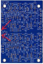
To confirm or rule out the JFETs being fried, you can measure the voltage drop over the associated resistors (I believe 10R ones? But can’t remember the exact value). Divided by 10 it should equate to approx 3mA for working JFETs.
Edit: please measure voltage drops across R1, R2, R4 and R5 for both channels and post here. Perhaps we can avoid a total rebuild.
And to state the obvious, don’t forget to triplecheck that your PSU is providing both negative and positive voltages into the circuit (confirm connected wires) just to avoid a blunder there.
Yes, check voltage drop across resistors: https://www.diyaudio.com/community/threads/waynes-ba-2018-linestage.329240/post-7747995
Hello everyone.
I am happy to be part of this forum. I am very happy to have Wayne's card.
Thanks to Wayne for this card.
I have a question about adapting the card to the Nelson PASS F4 amplifier.
How do I increase the gain?
I know this subject comes up a lot in this forum and answers have been given but nothing about appropriate values like an abacus for example.
For those who have an F4, what value of R7 (or other resistor) should be changed to have a good compromise?
Thank you in advance for your indulgence and your answers.
Best regards.
PS : sorry for my English, I'm French 😉
You can increase the gain of the circuit, but to drive the F4 with proper voltage swing, transformers are advisable. For example, see Myleftears posts a few years back for how to implement.
Here are some of myleftear‘s rambling around the topic:
https://www.diyaudio.com/community/threads/waynes-ba-2018-linestage.329240/page-122#post-6635749
https://www.diyaudio.com/community/threads/waynes-ba-2018-linestage.329240/page-123#post-6636208
Re-reading those … conversations, it was a fun time I must say!
https://www.diyaudio.com/community/threads/waynes-ba-2018-linestage.329240/page-122#post-6635749
https://www.diyaudio.com/community/threads/waynes-ba-2018-linestage.329240/page-123#post-6636208
Re-reading those … conversations, it was a fun time I must say!
… just as a guy called „zen mod“ predicted, I happened to use exactly those transformers in another build. Made me want to retry the thing 


I recently threw together an "iron pre" using a couple line transformers on the output of a Schitt Magni Heresy headphone amp. I also received the Fiio K11 R2R I had ordered. Initially I thought the DAC was terrible. The midrange sounded way too prominent and the treble was just grating my ears. A couple days pass by and I remembered the M2 had a zobel to tame the rising response from the transformer. So I decided to try that. I don't have any measurement equipment so I just used the values used in the M2(10K ohm resistor and 680pF cap). Turns out the Fiio DAC is not so bad. The harshness was from the peaking response from the transformer. Might be something to consider if anyone is looking to add output transformers to their WLS.
that applies for Edcor, as used in M2
later, Pa didn't compensate neither Jensen nor Cinemag repeaters
later, Pa didn't compensate neither Jensen nor Cinemag repeaters

not matter of quality, just implementation
more clearly, matter of approach in construction of xformer; said Edcor is nominally 600R:15K jobbie
most likely, if loaded with strictly 15K, it wouldn't need any compensation
we are using it slightly differently, thus Pa made what's needed
some other xformer is going to need some RC, some other not, depending how it's made
I have a dead board (new version, not the purples). Is there a schematic with target voltage ranges at various points in the circuit somewhere in this forum? Or, in the interest of continuing my education, is there a productive method for using a DMM to hunt for circuit problems? Thanks.
- Home
- Amplifiers
- Pass Labs
- Wayne's BA 2018 linestage