okidoki
proceed as said - change these resistors
I believe you called those "puny" inputs over on the Iron Pre thread.😀
Speaking of my TV as an input choice. Some times movie volume is low compared to typical "music" sources.
Russellc
And the Royal Mail will add their £8 for handling an import.
Wayne, I wish I was capable but alas I'm fairly green to all this. Thankyou for the design though.
And it would seem I cant buy the boards from the store anyway due to a Brexit issue. Well I could for a cool mil.!
Luckily a member has offered me a spare pair of his early pink boards here in the UK. Happy days.
Jim K I have a spare blue one and all semiconductors for the small output/standard version. Just give me a chime if interested.
I'm afraid this changes 1 July. As of then you will pay always VAT no matter what the price is.
Correct. The UK has implemented this change on January 1st 2021, and the EU is implementing it on July 1st 2021.
I have updated the Brexit information page with more detail:
Brexit VAT Changes – diyAudio Store
We have been working for several months in the background, on being able to offer UK and EU customers a "Delivered Duty Paid" (DDP) service. This will allow us to keep shipping low value parcels into the UK and EU in the future.
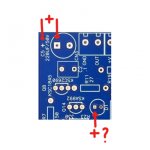
Question! I could be wrong but I always considered the square solder path to be - (minus). The PCB clearly states that the capacitor + (positive) should be soldered at the square solder path.
I the square solder path also the + (positive) side of the LED?
I the square solder path also the + (positive) side of the LED?
Attachments
Leuwarden,
The flat side of the emblem near D1, is for the cathode lead of the diode, D1. The anode lead is inserted in the hole where you have labelled in red +?.
Best,
Anand.
The flat side of the emblem near D1, is for the cathode lead of the diode, D1. The anode lead is inserted in the hole where you have labelled in red +?.
Best,
Anand.
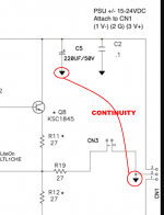
When in doubt: buzz it out. Using the continuity tester / beeper feature of your DVM.
The schematic tells you which terminals of which components, should be connected together by PCB traces. Get out your continuity tester and verify. There's only two terminals on C5, so there are only two possibilities to test: which of them has continuity to the middle pin of CN1? That's the MINUS terminal of C5! You've done it!
Square terminals vs non square terminals on PCB layouts, are placed at the whim of the PCB designer. The shapes have no meaning to anyone but her/him, and different PCB designers use them differently. Some PCB designers only use round terminals; no square ones anywhere. Other designers mix them at random.
Continuity testing, on the other hand, is a firm guarantee. Whichever terminal is connected to the places where the "-" terminal is supposed to go, IS THE MINUS TERMINAL. No matter what the shape of its copper soldering pad.
When in doubt: buzz it out.
_
Attachments
MJ is right! Best to learn and associate with the schematic instead of associating symbols if something doesn't make sense or needs verification.
Best,
Anand.
Best,
Anand.
I agree that is the ideal way. But Leeuwardens question was regarding this specific circuit, not in general. The long lead goes in the square hole regardless on this specific circuit, and many know this. Good thing that the wizards assistant/maker had to turn up to provide this simple answer to someone just trying to finish without further adue. For some, the mere soldering process on these boards is a challenge. I perfectly understand why Leeuwarden asked this question, and I don’t think it is fair to procastrinate the answer instead of just providing it. Yes, it is possible to deduce the answer from the circuit. It is however just as possible to just help the guy.
And the Royal Mail will add their £8 for handling an import.
Wayne, I wish I was capable but alas I'm fairly green to all this. Thankyou for the design though.
And it would seem I cant buy the boards from the store anyway due to a Brexit issue. Well I could for a cool mil.!
Luckily a member has offered me a spare pair of his early pink boards here in the UK. Happy days.
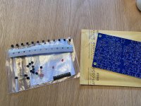
Hi, James!
Finally found the time to collect the stuff I promised you. Depicted are all semis required for the standard circuit. I also threw in some original Lite-On LEDs and 220pF Wimas, along with the PCB. I’ll ship it to you tomorrow.
There are two extra of all semis, in case you screw up

I don’t know how experienced you are, but start with the JFETs, and plan and prepare for the job, and do a beep test in diode mode afterwards. And clean, yes clean. Liquid flux is preferable, and apply with pen or toothpick to pads. Currents are low and small errors equate to instability. It is an extremely stable circuit if done right. I know, I always mess up the first time
as I did on this circuit too. But what a learning process.Good luck!
Attachments
OTOH, it is extremely precious to know a square terminal hasn’t a specific clear meaning… (only trust a square terminal after you found out what it stands for on the specific board)… or, well, never forget to doublecheck it [emoji6] and find the other signs on the board, likethe flat part of the diode‘s outline.
Hi, James!
Finally found the time to collect the stuff I promised you. Depicted are all semis required for the standard circuit. I also threw in some original Lite-On LEDs and 220pF Wimas, along with the PCB. I’ll ship it to you tomorrow.
Good luck!
Andy what can I say other than a huge thank you. You are a gentleman.
Shall PM you regarding payment!
Thanks again
I have to agree a bit here. I think that a combo of both answers would be ideal: "X leg goes into Z whole in this board. For future similar issues, the convention is Y, the easiest way is to buzz in, etc., etc., etc."....and I don’t think it is fair to procastrinate the answer instead of just providing it. Yes, it is possible to deduce the answer from the circuit. It is however just as possible to just help the guy.
All these "teach a man to fish" answers are great, but for those that are new, or those that know very little, or those that are into this hobby to create the final thing and not know much of the inner workings (of which for sure there are some exponents here), I agree that giving the straight answer and then the 'extra stuff' could be more "friendly".
I am myself almost done reading all this thread in order to start my own build. PSU is proving more complex than expected (source from, at least, two or three different places PCB, parts and transformer), and I haven't yet decided on the POT, learning about Shunts, Stepped, Relays, and what-not and haven't even gotten to the input selector craziness of all the options 🙂.
That's part of the fun of this, but juggling all that info at the same time can be daunting the first time you are dealing with all the complexities. Even more so if you need to coordinate shipments abroad.
Really excited about this project!
Andy what can I say other than a huge thank you. You are a gentleman.
Shall PM you regarding payment!
Thanks again
Giving something back is the least I can do. This community is awesome. I promised 6L6 to return his favour to someone else some time, and I am simply honoring that. Others too have shown me the same courtesy. Hope it all arrives safely and that you get to enjoy this wonderful circuit! Don’t sweat payment. Join me for a beer after BAF, at the Trubadour or something, and I am happy. Cheers
Last edited:
PSU is proving more complex than expected
If you are interested, here's the power supply I used for my BA2018 line amps. It is the regulated Whammy PS with LED references, designed by Wayne Colburn, laid out on a new PCB design, sized to fit the Hammond chassis he originally used.
Attachments
Join me for a beer after BAF
You will attend BAF?
:very cool: [emoji41]
Thanks so much! I actually have already built the Whammy, so it should be straightforward, it’s something I know how to build and test, and it is kind of my “fallback” plan. I was hoping to build something new like the VRDN or the Helios from Audiosy. First to learn something new, but also with the appeal of fine tuning the voltage with pots, perhaps the de-noisier, etc.If you are interested, here's the power supply I used for my BA2018 line amps. It is the regulated Whammy PS with LED references, designed by Wayne Colburn, laid out on a new PCB design, sized to fit the Hammond chassis he originally used.
Still, sourcing the parts requires some substitutions as some parts are out of stock and I am asking to their respective designers in their respective forums / mails. I am not having too much of luck with replies.
I’ll give it an extra try, and, should everything else fails, yes, I’ll default to the tried and tested Whammy PSU.
Those files are a very convenient bonus, I was actually thinking of giving a go at designing the PCB myself, but those efforts can be channel to something else now.
Thanks again!
Rafa.
Thanks everyone for answering my question. Especially Mark for explains how to handle!
When in doubt: buzz it out. Using the continuity tester / beeper feature of your DVM.
The schematic tells you which terminals of which components, should be connected together by PCB traces. Get out your continuity tester and verify. There's only two terminals on C5, so there are only two possibilities to test: which of them has continuity to the middle pin of CN1? That's the MINUS terminal of C5! You've done it!
Square terminals vs non square terminals on PCB layouts, are placed at the whim of the PCB designer. The shapes have no meaning to anyone but her/him, and different PCB designers use them differently. Some PCB designers only use round terminals; no square ones anywhere. Other designers mix them at random.
Continuity testing, on the other hand, is a firm guarantee. Whichever terminal is connected to the places where the "-" terminal is supposed to go, IS THE MINUS TERMINAL. No matter what the shape of its copper soldering pad.
When in doubt: buzz it out.
_
You will attend BAF?
:very cool: [emoji41]
I plan to join you in the CDG lounge in Paris some time, and we can go together
- Home
- Amplifiers
- Pass Labs
- Wayne's BA 2018 linestage