I replaced some jfets and things got worse. I re-flowed them again and things got a little better. I readjusted the output from the VRDN boards to exactly 18v again, and adjusted dc offset, and now everything seems to measure properly. So, I have no idea if it's truly fixed or not.
Thought I'd hook it up and see what it sounded like but realized very quickly from the foreboding hum that I did not properly ground my RCA inputs and outputs.
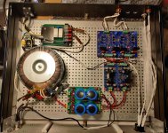
Right now I've got the mains and the VRDN boards grounded to the case bottom. I connected all of the the line level signal cables to the source selector and volume pots, but that obviously wasn't the best idea. I've been reading forum posts and white papers for two days now, and feel like I know a lot more, but not what to do.
Should I just connect all of the signal grounds to the case?
Thought I'd hook it up and see what it sounded like but realized very quickly from the foreboding hum that I did not properly ground my RCA inputs and outputs.
Right now I've got the mains and the VRDN boards grounded to the case bottom. I connected all of the the line level signal cables to the source selector and volume pots, but that obviously wasn't the best idea. I've been reading forum posts and white papers for two days now, and feel like I know a lot more, but not what to do.
Should I just connect all of the signal grounds to the case?
regarding hum and noise....
http://hifisonix.com/wordpress/wp-content/uploads/2019/02/Ground-Loops.pdf
Some very good information here. I particularly like the practical examples in the second half of the presentation.
http://hifisonix.com/wordpress/wp-content/uploads/2019/02/Ground-Loops.pdf
Some very good information here. I particularly like the practical examples in the second half of the presentation.
Hi Guys, as a newbie to electronics and new to DIY Audio, with the help of the forum, I successfully completed the F5T as a dual mono-block design. I am so impressed, I’d like to attempt Wayne’s Burning Amp Linestage. I pretty much have all the material including using Muse’s volume control and electronic display. Can anyone suggest a chassis that would be suitable to use? Thank you in advance
This depends a lot on what you‘re going to run it with:
- PSU
- volume attenuator
- source selector
Also, maybe you plan to include a DAC and or Phono-section?
I have my VRDN with a toroidy 2x15v 50va, VRDN, Salas i-select, 2 elma relay volume attenuator, and even planned to use a pair of cinemag output transformers (for gain, but ditched this) and fit all this into a modushop galaxy 1U 330x230… all this fit nicely, could even insert a small transformer for the relay sections!
@myleftear- Thank you for the input. I think this time around I will keep it pretty basic with a power supply, volume attenuator, input selector and input card. Do you know what the best way is to cut out for the digital display?
I replaced some jfets and things got worse. I re-flowed them again and things got a little better. I readjusted the output from the VRDN boards to exactly 18v again, and adjusted dc offset, and now everything seems to measure properly. So, I have no idea if it's truly fixed or not.
Thought I'd hook it up and see what it sounded like but realized very quickly from the foreboding hum that I did not properly ground my RCA inputs and outputs.
Right now I've got the mains and the VRDN boards grounded to the case bottom. I connected all of the the line level signal cables to the source selector and volume pots, but that obviously wasn't the best idea. I've been reading forum posts and white papers for two days now, and feel like I know a lot more, but not what to do.
Should I just connect all of the signal grounds to the case?
Hum might have many causes. To rule out the JFETs, measure R1 and R2 and their equivalent voltage drops on the other channel to get four readings. Also note how stable those readings are. If they are dissimilar or unstable, you still have JFET issues. If stable and alike (around 3mA give or take), proceed to wiring. Offset drift at the outputs should be no more than +/- 0,1mV read rapidly, and +/-1 mV read over time (after equilibrium and in case), IMOE.
In general I like to have absolutely none of the signal grounds attached to chassis, as a starting point. I have only 1 - one - gnd cable going to chassis, and that is PSU gnd, and it is not directly connected to the chassis, but through a ground loop breaker. The audio gnds join hands at the PSU gnd. Dead silent on first go. 6L6 posted a hand written schem in this thread and I followed it.
Of course, what works will vary from build to buld, and attenuators for example may have different needs.
But as a general rule, never connect signal/audio gnds to chassis, and absolutely never directly. If you have to, something is most often amiss. Audio/signal gnd and chassis gnd are not the same!
Hope you solve it.
Andy
Regarding to Audio-input, I put an 0.1uF Y2 between Input-GND and chassi. I did the same in Whammy(see Waynes presentation 27min 16sec). The linestage is dead silent with isolated standoffs for pcb.
Good point. Such a solution can make a even quieter gnd, particularly for hf, but not doing it should not cause hum on the WLS.

…keep it pretty basic
…best way is to cut out for the digital display?
So you could go with an even smaller case! 🙂
(I recommend to make a moch chassis out of card-board or anything easily workable—priceless to have a plan for a nice layout!
For a display-cutout, best of course is a laser (but that’s pricey, too)
For non-round holes (that can be „flat cuts“ / don’t need a special cross-section, I go the brutal way: drill holes around it with enough tolerance to avoid getting out of the cutting and file it down very gently. If you’re careful, you can achieve 0.1mm precision…
There are other options available if you have access to a metal-workshop, though…
[emoji1320][emoji28]
Thabktou.
I was aware of the store boards. I'm happy to pay the store prices but the import to the UK gets costly. Hence me asking after gerbers.
Thanks for your time though
WLS in old BA3-chassi for testing. I use a carbon extender for the pot. Maybe that could contribute to noise when touching knob. Carbon extender is linked to pot with armoured fuel hose. It sounds fantastic with F4.
Looks fantastic!!
So you could go with an even smaller case! 🙂
(I recommend to make a moch chassis out of card-board or anything easily workable—priceless to have a plan for a nice layout!
For a display-cutout, best of course is a laser (but that’s pricey, too)
For non-round holes (that can be „flat cuts“ / don’t need a special cross-section, I go the brutal way: drill holes around it with enough tolerance to avoid getting out of the cutting and file it down very gently. If you’re careful, you can achieve 0.1mm precision…
There are other options available if you have access to a metal-workshop, though…
[emoji1320][emoji28]
Thank you for that. I think I may give it a shot.
Margol,
Nicely done!
I like your use of a rectifier as a ground fault device and to minimize potential ground loops.
You did a good job minimizing the path length from the output of the Super Reg’d supply to Wayne’s BA2018. This makes sure that the supply impedance is kept as low as possible which is one of the advantages of the that supply. Let us know what it sounds like!
Best,
Anand.
Last edited:
Giving out the Gerber fab data is giving the design away for free. That was not Wayne’s intention. As they say, pay the piper. You can always design your own, the schematic is public domain. Credit goes to Wayne and Scott.Thabktou.
I was aware of the store boards. I'm happy to pay the store prices but the import to the UK gets costly. Hence me asking after gerbers.
Thanks for your time though
Last edited:
- Home
- Amplifiers
- Pass Labs
- Wayne's BA 2018 linestage