It looks like you build a compressor. It woiuld be of interest to see how the distirtion changes when the conmpressor becomes active.
BTW Organising the gain structure so that the preamp clips before the poweramp can also be of interest.
Jan
BTW Organising the gain structure so that the preamp clips before the poweramp can also be of interest.
Jan
As to a low leakage diode - did anyone mention the FDH300? I did extensive testing for my autoranger protection .....
Jan
Jan,
Did you try BAS716 ?
How does it compare ?
Patrick
This amp has two parts (it is integrated type), preamp with no GNFB and OPS with GNFB and gain of two. The volume control is after preamp part.
This anti saturation circuit is to prevent OPS to saturate. The distortion is quite low and start to increase wen zeners start to conduct of course.
Why is important how distortion changes when anti saturation circuit (I would not call it compressor) become active?
This anti saturation circuit is to prevent OPS to saturate. The distortion is quite low and start to increase wen zeners start to conduct of course.
Why is important how distortion changes when anti saturation circuit (I would not call it compressor) become active?
I made this softclipper with simple LED's:I've come up with an unusual amplifier topology involving boostrapped stuff, and that seems to have, shall we say... non-optimal clipping behavior. So it looks like I'm going to need a pre-clipping circuit.
Of course it should not distort at all until it does.
I've sketched a number of attempts, all involving bootstrapping the clipper diodes to reduce distortion by keeping voltage across them constant, which avoids nonlinear capacitance effects, leakage, etc. The bootstrap voltage is itself clipped by another pair of diodes, so when it reaches the limit, the other side of the diodes no longer follows the input signal and they begin doing their job.
The four ones on the left use diodes or transistors as diodes. They're strictly at the input of the amp, so they need an opamp buffer for the bootstrap voltage. The one on the right deletes the opamp by using the amp's output voltage (the power amp is VCVS E1) and using BJT emitter followers as diodes. Basically the two transistors' bases follow the input signal so they do nothing, until the diodes on the right conduct, at which point the transistors limit the input signal.
On the left is a sinewave with a smashed top.
View attachment 1071619
And here is THD vs input level. Simulations are sometimes slightly optimistic, but it looks like "no distortion before it has to begin clipping" is achievable.
View attachment 1071625
Thoughts?
https://www.diyaudio.com/community/...-8-ohm-how-to-limit-power.421941/post-7890159
https://www.diyaudio.com/community/...-8-ohm-how-to-limit-power.421941/post-7890258
Its TDH < 100dB upto -9dB with softly increasing distortion above that, very happy with the solution and you can see when it triggers 🙂
Last edited:
You would want to know how rapid the distortion rises at the onset of overload. How much better is it than just clipping?This amp has two parts (it is integrated type), preamp with no GNFB and OPS with GNFB and gain of two. The volume control is after preamp part.
This anti saturation circuit is to prevent OPS to saturate. The distortion is quite low and start to increase wen zeners start to conduct of course.
Why is important how distortion changes when anti saturation circuit (I would not call it compressor) become active?
Jan
Indeed, looking at datasheets for BC327 and BC337 (several manufacturers) show VBEo MAX as 5V. I've seen reverse-biased B-E junctions of transistors used as noise generators in the 5 to 10V range where they have a zener response, but somewhere I've read advice against doing this, that it damages the transistor/reduces HFE. Then again that may not much matter in this circuit.It appears to me that in the circuit of post #150, transistors Q13 and Q14 operate in the reverse active mode.
This is a bit unusual for audio circuits, and I worry that transistor behavior in this mode is likely to have a much greater variance, both from unit to unit, and from low temperature to high temperature. Simulation DC bias result shown below.
- NPN Q14 has (VBE = -10V) and (VCE = -10.5V)
- PNP Q13 has (VBE = +10V) and (VCE = +10.5V)
You can see from rounded edges when clips that distortion is not abrupt, and the main advantage is that OPS does not clip, as there is no saturation.You would want to know how rapid the distortion rises at the onset of overload. How much better is it than just clipping?
Jan

If I insert a resistor in series with those zener diodes the clipping is much softer.
First one is just on the brink of the clipping, second one is dip in the clipping.
First one is just on the brink of the clipping, second one is dip in the clipping.
Attachments
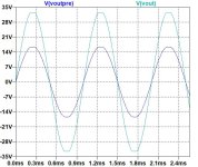
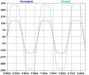
From the graphs it apperas that with the series resistor there is less gain, and that results in less clipping.
It is very hard to judge things from a scope screen with many other factors not known.
The best is a graph of distortion versus output level in the various conditions.
Jan
It is very hard to judge things from a scope screen with many other factors not known.
The best is a graph of distortion versus output level in the various conditions.
Jan
Hi Jan,Looking forward to your build.
I built it and this is how it looks like:
The module has two channels.
I also measured it with the threshold set very low ahead of a balanced input, which has a connector mating with this module.
I swapped the module with jumpers back and forth.
Just prior to clipping, distortion was not measurable independent of frequency.
In my mind, it does not make any sense that distortion of this circuit rises with increasing frequency.
I believe the simulation is wrong.
As long as the operational amplifier can drive the other side of the diodes to the same potential as the signal, there is zero voltage across the diodes.
Means the op-amp would need to distort enough that there is a delta voltage that allows a bit to creep through the diodes.
Of course, distortion gets worse with rising frequency, especially with such budget amplifiers, but it would need to be really heavy to generate substantial delta.
I found some fast recovery diodes for the built, but could not record clipping yet, because I gave up improvising an adapter for the measurement.
I will design a proper test jig instead. I have more similar modules sharing this connector and need a proper adapter anyway.
Distortion free Distortion setup?, use the last 10% of amp voltage to compress the signal. Properly biased tube 12AX7 can work well.
Tubes will also "fatten" the waveform before clipping. I estimate the 6922 preamp gives me at least 3db extra headroom
Tubes will also "fatten" the waveform before clipping. I estimate the 6922 preamp gives me at least 3db extra headroom
I agree in principle, except my guess would be the last 50-75% of amp voltage. Seems outrageous at first glance but it's only 6-12dB of cushioning.
Maybe some kind of listening test is in order? Perhaps a Python script to apply test-run some different compression curves?
Maybe some kind of listening test is in order? Perhaps a Python script to apply test-run some different compression curves?
One factor to consider is that opamp input difference voltage is usually assumed zero but it isn't - it is Aol/Vout.As long as the operational amplifier can drive the other side of the diodes to the same potential as the signal, there is zero voltage across the diodes.
Means the op-amp would need to distort enough that there is a delta voltage that allows a bit to creep through the diodes.
Of course, distortion gets worse with rising frequency, especially with such budget amplifiers, but it would need to be really heavy to generate substantial delta.
Since the open loop gain falls with frequency, input difference voltage increases with frequency and voltage across the diodes also increases with frequency for the same signal voltage.
That may explain increased distortion with frequency.
What I am amazed at is that nobody takes the trouble to do the one important graph, distortion versus input signal, that can easily show the relative performance of different solutions.
All 'designers' * appear to just waffle about it. Why?
Jan
* someone designing a circuit without showing the factual performance is not a real designer.
Attachments
This is a good & interesting thread.
I haven't read it all.
Has anyone posted the method of using a low distortion chip-amp to drive an incandescent bulb/globe of the appropriate value into
a suitable load to achieve a soft & subtle audio compressor with 'very musical attack & decay times' ?
I haven't read it all.
Has anyone posted the method of using a low distortion chip-amp to drive an incandescent bulb/globe of the appropriate value into
a suitable load to achieve a soft & subtle audio compressor with 'very musical attack & decay times' ?
Last edited:
I've thought about this, regarding guitar amps. One would think "REW" or something could do it as a frequency sweep, incrementing level bit by bit. This would result in a 3D plot, where you can select which harmonic to display. I could probably figure it out in LabView and my HP function generator with GPIB, but that's not something others could easily make use of like REW's FR generating and graphing functions.distortion versus input signal,
They somehow claim to emulate the dynamic behavior of different guitar amps using a fancy box with DSP. I wonder if this "distortion versus input signal" level analysis is what they start off with? If so, someone's done it to get what they want and productize the result.
It's a simple funntion in REW to graph distortion vs F or vs V.
One-click once REW is set up.
But even if it was hard, you'd still do it, right?
What is the point of discussing it without having a clue how it works?
A single freq sine wave with partly flattened tops tells you zilch.
Jan
One-click once REW is set up.
But even if it was hard, you'd still do it, right?
What is the point of discussing it without having a clue how it works?
A single freq sine wave with partly flattened tops tells you zilch.
Jan
Attachments

Every chart tells a different story and it useful on its own.
The waveform is useful to see whether the clipping is clean, or shows some ugly overhang / sticking (see my contribution with diode recovery issues).
The FFT tells a bit about the harmonics - more even or more odd ones. Higher odd ones would mean that clipping is symmetric, preferable IMO.
The level vs. THD chart tells about how abrupt or gradual it goes into clipping with increasing signal level, i.e. how much clean headroom there is prior to gradual or sudden THD increase.
What does the topic "distortion free soft clipping circuit" mean at all?
Distortion free probably means that THD should be very low below the clipping threshold. Not so easy as you pointed out.
Soft could mean that transition into clipping should be gradual instead of abrupt? Or that clipping is not ugly (time domain)?
THD vs. level is easy to measure using REW for example - do a sweep or even better stepped level increments for more accuracy.
In simulation, at least in LT Spice, it is among the advanced simulations IMO. Level would need to be stepped and the results plotted somehow. Takes a long time and needs knowledge how to do it properly. I haven't done this yet because I don't know how to do it. I've seen it somewhere, but remember it is not trivial.
In simulation, at least in LT Spice, it is among the advanced simulations IMO. Level would need to be stepped and the results plotted somehow. Takes a long time and needs knowledge how to do it properly. I haven't done this yet because I don't know how to do it. I've seen it somewhere, but remember it is not trivial.
I like to present a slightly different variant of the circuit I recently posted:

The idea is to simplify the circuit by replacing the transistors with Zener diodes as mentioned previously.
The Zener diodes have massive capacitors in parallel and those capacitors allow to sink AC currents far in excess of what the 500mW Zeners could handle.
The 1uF capacitors share the footprint with the 1000uF capacitors, hence cannot be installed simultaneously.
Unlike the previous circuit, this does not work for DC obviously, hence this circuit would be best placed after the DC coupling capacitors.
In theory, this circuit also works very well.
The PCB looks very similar:
@jan.didden, you are right that theory and practice deviate a lot.
In theory, the voltage across the op-amp inputs should be close to zero, in practice this is not the case at all.
Here is a simulation of the circuit using the near perfect LT Spice universal OP-amp type 1:

The amplifier is able to follow the signal well, except during transients.
Now with the ADTL082 model:

This amplifier architecture limits swing towards the negative power supply rail and while the clipping still looks right, the amplifier loses control entirely.
This limits the headroom of the circuit because there should be more margin towards the rails.
I simulated the circuit with many apparently suitable (J)FET amplifiers from the LT Spice library and the result was disastrous in most cases.
This is only one example:

The amplifier not only glitches during transients, there is also severe oscillation all the time.
If I hadn't started simulation with the ADTL082 model, I might have (wrongfully) dismissed the concept because it fails with 11 amplifiers I tried.
In my mind, the concept should work.
There is an inherent risk of a positive feedback loop and this is very obvious:
There is only a resistor and diode between the output and the non-inverting input of the amplifier.
Anything that may sneak through the diodes may turn this into an oscillator.
Meanwhile I also have the test jig complete and hopefully can present a full set of measurements next week.
Else, it will be next month after my vacation.
In theory, the voltage across the op-amp inputs should be close to zero, in practice this is not the case at all.
Here is a simulation of the circuit using the near perfect LT Spice universal OP-amp type 1:
The amplifier is able to follow the signal well, except during transients.
Now with the ADTL082 model:
This amplifier architecture limits swing towards the negative power supply rail and while the clipping still looks right, the amplifier loses control entirely.
This limits the headroom of the circuit because there should be more margin towards the rails.
I simulated the circuit with many apparently suitable (J)FET amplifiers from the LT Spice library and the result was disastrous in most cases.
This is only one example:
The amplifier not only glitches during transients, there is also severe oscillation all the time.
If I hadn't started simulation with the ADTL082 model, I might have (wrongfully) dismissed the concept because it fails with 11 amplifiers I tried.
In my mind, the concept should work.
There is an inherent risk of a positive feedback loop and this is very obvious:
There is only a resistor and diode between the output and the non-inverting input of the amplifier.
Anything that may sneak through the diodes may turn this into an oscillator.
Meanwhile I also have the test jig complete and hopefully can present a full set of measurements next week.
Else, it will be next month after my vacation.
- Home
- Amplifiers
- Solid State
- Wanted: distortion free soft clipping circuit