
so a very valuable lesson i heave learned here
the c1400 transistor fitted does not have the pin out that all of the web pages and thier tech sheets suggest
The base is pin 3 not 1,which now makes perfect sense as what i thought was BCE, was in fact ECB,and this realy makes sense now how it all snowballed into days of going round in circles, having fitted the BD139 unit in its place thinking all i was doing was reversing which way it faced,(these are ECB) and as a result ended up with -24v on the output, and as a result -24v on the other channel(remember when i swapped over the 2 transistors to see if it was that and ended up with even more trouble.)
I will never trust or take for granted anything again going forward.
I replaced the c1400 with a BC549c and have had it playing away now for hours(touch wood)
but it certainly appears the c1400 had a fault with it that was appertained primarily with load/current/voltage when the volume was increased, this is what the noise issue turned out to be, as this only appeared when the voltages at the terminal went haywireat higher volumes.
so a 2 hour job turned into days, and i will never have to go through that again because i took things for granted👍
Well done 🙂 you always have to be on your guard for things like that, and also errors in diagrams.
You will also find with fault finding (as here) that if you look back on it all having fixed it that all the evidence was probably there, its a case of piecing it all together. That's one reason I always enjoyed fault finding, its like forensic detective work sieving through all the evidence.
You will also find with fault finding (as here) that if you look back on it all having fixed it that all the evidence was probably there, its a case of piecing it all together. That's one reason I always enjoyed fault finding, its like forensic detective work sieving through all the evidence.
oh absolutly, dont get me wrong, i enjoy it alot, i would rather not though spend 4 days finding something,that had other info been correct, would have been half a day at best, but there you go🙂, and i should also learn more to trust my own intuition, as it has proved me right so many times with other things in the past, and what was the first thing i looked at and kept looking at? Q601Well done 🙂 you always have to be on your guard for things like that, and also errors in diagrams.
You will also find with fault finding (as here) that if you look back on it all having fixed it that all the evidence was probably there, its a case of piecing it all together. That's one reason I always enjoyed fault finding, its like forensic detective work sieving through all the evidence.
but there you go.Tea time☕
and my next one is, yep you guessed it, same model.This unit has very distorted sound
ill start a new thread with this one, even if i dont have problems with anything ill still post so it may help others going forward
ill start a new thread with this one, even if i dont have problems with anything ill still post so it may help others going forward
I've just had the Penguin 😉 Trusting your instincts is something that will come in time. When you start out you can't quite believe that printed manuals can be in error or that parts can be different.
Long before internet and fake parts were an issue I got some NPN and PNP MPSA something or others from a major supplier and odd ones of each batch were of the opposite polarity i.e. NPN instead of PNP.
Found it:
https://www.diyaudio.com/community/threads/my-transistors-original-or-copy.82638/post-1311453
and my next one is, yep you guessed it, same model.This unit has very distorted sound
So a perfect candidate to look at the distortion on the scope using the signal generator as a source. Around 1kHz and with and without a load resistor.
Simples
Have you ever heard of this site? which has copies of all many popular magazines.
https://worldradiohistory.com/
Have a look at Wireless World from August 1993 (and for some months after) for Doug Selfs series on amplifier design. You might find it interesting. Left hand menu for all the titles.
All the mags load as pdf's
https://worldradiohistory.com/
Have a look at Wireless World from August 1993 (and for some months after) for Doug Selfs series on amplifier design. You might find it interesting. Left hand menu for all the titles.
All the mags load as pdf's
interesting reading
i am right in that if a cap is to ground it should be near to 0v
I have a cap C613, same amp its 800mv one side and -150mv the other, so this is suspect right? Its a poly
And although ive been using this all morning i realy ramped it up a little while ago and it started to wander a bit again, so i thought id check out some of the caps as you suggested.I did do this yesterday but only the ceramic ones
could poly ones go duff? ive not had it before
also when i check the ground continuity from the cap to ground its about 45ohms
Last edited:
so this is a mylar cap 1nf so i replaced it, but i only had a 1.2nf, i presumed this would be ok, but now its even more distorted,and i still have over 250mv between it and ground
im going to put the bottom cover on in case its relying on a connection somewhere see if that helps
im going to put the bottom cover on in case its relying on a connection somewhere see if that helps
i am right in that if a cap is to ground it should be near to 0v
Easiest answer is yes, one end of the cap should be at the same voltage as 'ground'. That is normally zero volts. The other end of the cap can be at any DC voltage as dictated by the circuit.
Ground does not always have to be zero volts... it usually is but is does not have to be. Remember voltages are always measured with respect to another point. All components that connect to the same ground should always have continuity between them.
C613 (1nF) in that NAD diagram should connect to every other part that is marked as going to ground. So if you have 45 ohms then that needs looking at. Easiest way to be sure is to follow the print and see if it really is ground.
Its very very rare for a poly type cap to fail in these kind of applications. It just doesn't happen as a rule.
so they are to ground if you use the transformer ground as the reference.The casing appears not to be that reference as none of the component grounding references have continuity to case ground, only transformer ground.Now when i did this yesterday and connected both together r634 went up in smoke, and i just reconnected it and the resistor started to burn again.Easiest answer is yes, one end of the cap should be at the same voltage as 'ground'. That is normally zero volts. The other end of the cap can be at any DC voltage as dictated by the circuit.
Ground does not always have to be zero volts... it usually is but is does not have to be. Remember voltages are always measured with respect to another point. All components that connect to the same ground should always have continuity between them.
C613 (1nF) in that NAD diagram should connect to every other part that is marked as going to ground. So if you have 45 ohms then that needs looking at. Easiest way to be sure is to follow the print and see if it really is ground.
Its very very rare for a poly type cap to fail in these kind of applications. It just doesn't happen as a rule.
so this is the current cenario
right channel works perfectly right up to full volume
left channel is distorted and you can here it get more distorted as the voltage increases at the terminals and as you raise the volume
if there was a ground issue wouldnt the right channel be affected?
if i use the case as ground reference
i have -250mv with a load
with no load 46 ohms
if i use the transformer as the reference all are 0v
so you could say they are correct realy
why the case ground isnt reference i dont know but i have checked a couple of other amps and they are the same so it must be correct and im not going up a blind ally with that one.
i just have to find the source of the distortion somehow
Last edited:
if there was a ground issue wouldnt the right channel be affected?
Not necessarily because a ground problem might be effecting just one channel.
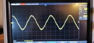
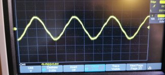
Look with the scope at what the distortion looks like, it might give a clue. For example on a sine wave you might see the top or bottom half distort which would point the one or other half the output stage.
ok ill give this a go in the morning.I think it is something simple.Not necessarily because a ground problem might be effecting just one channel.
Look with the scope at what the distortion looks like, it might give a clue. For example on a sine wave you might see the top or bottom half distort which would point the one or other half the output stage.
Erm....It seems you've created a quandary there, considering your new avatar. Unless you've been there before with an similar product and symptoms, an open mind is more likely to lead to success and less time wasted on proving something doesn't work when it probably does or vice-versa.
There are an awful lot of Ebay bodger-recyclers out there who think anything that makes sound is a good repair job but that's what destroys the ubiqutous old NAD 3020s that might otherwise have lived until the chassis rusted away. About them, I can only say; don't join their ranks. Brush up on your high school physics and study the audio electronics books and sites Mooly suggested. There are also plenty of tedious tutorials out there on the web too - no point in trying to study when you're falling asleep though, so pick carefully according to your current level of education and the presenter's communication skill.
There are an awful lot of Ebay bodger-recyclers out there who think anything that makes sound is a good repair job but that's what destroys the ubiqutous old NAD 3020s that might otherwise have lived until the chassis rusted away. About them, I can only say; don't join their ranks. Brush up on your high school physics and study the audio electronics books and sites Mooly suggested. There are also plenty of tedious tutorials out there on the web too - no point in trying to study when you're falling asleep though, so pick carefully according to your current level of education and the presenter's communication skill.
Last edited:
Ian i am the complete opposite.
I have a very open mind, the recent avitar represents what i consider as a very good mind set.
My objective is to properly repair and put back out a good quality product, and nothing leaves this premises untill i am 200% sure it is the very best it can be and i am not in the habit bodging anything.
I am not in this to even make a profit out of anything,i dont need the money, i do it because i enjoy it.
I have some exceptional feedback on the items i have brought back to life and i take great pride in what i do.
This is part of my learning and i do look at and study what is given to me, but i am not a uni student, and am not likely to be at my age.
My objective is to learn ,yes, but to a level that is to my compitency level, and also realistic, given i have a very intence full time employment to deal with 5 days a week, like many others.
but i appreciate and take your comments on board 👍
Im hoping i have done this correct.ok ill give this a go in the morning.I think it is something simple.
pictures of the sine wave at full volume
this is AC coupling though, not DC, you didnt mention what it should be, but i can do it again in DC if i need to.
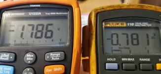
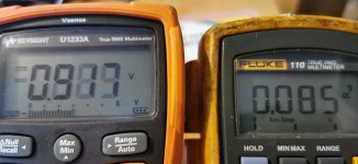
also some pictures of the offset L/R at volume 0, mid and full volume
I have triple checked everything on the output side and there is very little or no difference with the voltages from one end to the other when there is no load
The issue now is definatly attributed to when the volume is raised and current increased so i will keep plodding on.
the difference is the original problem was it was wandering without touching anything form zero to +/- 2v
so i i think know where we are at with this.Not necessarily because a ground problem might be effecting just one channel.
Look with the scope at what the distortion looks like, it might give a clue. For example on a sine wave you might see the top or bottom half distort which would point the one or other half the output stage.
The offset is fine while its sitting doing nothing, so im not going to be chasing a problem that isnt there.
im pretty sure the issue is with the grounding somehow
i compared another 3020 and measured to ground from the chassis C613
on my amp its over 400mv
on the other amp its less than 1mv, so i guess its leakage from a component.??
i guess the only way to find this now is process of elimination by removing a leg from each one untill i find the one that is leaking because the voltage is common across ground.
question is can i safely remove a leg with the power on without damaging the amp.
Attachments
If you are comparing two identical models then it just sounds like there is a floating ground somewhere. Depending on what any ground resistance was would have a a big impact on the voltage between those two points.
So I wouldn't automatically say something is passing current to ground. Currents do flow to ground from parts that connect to ground but the whole point of a low resistance ground path is that those currents would not generate any voltage.
The scope shots are a little inconclusive I'm afraid.
Can you not just physically follow the copper print from C613 and see where it goes?
yep i did do all that.If you are comparing two identical models then it just sounds like there is a floating ground somewhere. Depending on what any ground resistance was would have a a big impact on the voltage between those two points.
So I wouldn't automatically say something is passing current to ground. Currents do flow to ground from parts that connect to ground but the whole point of a low resistance ground path is that those currents would not generate any voltage.
The scope shots are a little inconclusive I'm afraid.
Can you not just physically follow the copper print from C613 and see where it goes?
There must be something amiss though isnt there if one exact model has a cap with 1mv to ground as i guess it should be and the other is 0ver 200mv? as are all the other components to ground. they all have the same value on them
I cant think of anything else realy that would make the centre drif along with volume increase
everything without a load is exactly as it should be.both channels have the correct voltages all over, very little difference, so what ever it is, has to be common throughout, and i cant think of anything else at the moment that is more common, than the grounding.anyway im packing away for this week, im just about done in.
Its difficult at a distance to imagine what is going on with this.
You could try connecting the scope probe ground to a known good ground point and then looking with the scope at parts that are supposed to go to ground. Of course you should see nothing as you are looking at what are electrically the same points but if you have floating grounds you will see something.
The speaker negative terminal is a high current point and that has to connect to the main reservoir cap ground. So electrically that shuld read zero ohms from socket to reservoir caps and from there to C613.
- Home
- Amplifiers
- Solid State
- wandering centre nad 3020 ser 20