I have decided to try the Sanyo 2SA1538 2SC3593 pair at the VAS in one pair of boards and compare with the ones on the schematic. Don't know if I'll hear any difference but the Hfe curve looks better. Of course they can look good on paper but not be so good in person. I'll give them a listen.
http://www.sm0vpo.com/_pdf/2SA/2SA1538.pdf
http://www.sm0vpo.com/_pdf/2SA/2SA1538.pdf
...
Jason's tests with a curve tracer indicate a lower knee in the gain curve than what one might expect based on the datasheets. Post 218 and 219.
...
I set up the parameters of the curve tracer to focus on our area of interest in the 10-20mA range. If I alter some of the settings I can generate curves that extend out further on the current scale at the expense of resolution in our region of interest. Seems a bit of a compromise is needed when doing some of these evaluations. I'm still evaluating various settings to see what works best for different devices.
Have you gotten those alternative devices I sent yet? I expect they would likely sometime this week. Then again, with customs these days who knows.
Great idea, although I cannot find these stocked at the usual distributors.I have decided to try the Sanyo 2SA1538 2SC3593 pair at the VAS in one pair of boards and compare with the ones on the schematic....
The range in your graphs corresponds well to my area of interest, but for other people, perhaps you could extend it to 30 mA. It should probably extend about 10 mA above the intended bias current. I believe that Lazy Cat specifically recommended not to increase the bias much past his recommended 12 mA, but I am sure someone will want to do it (chuckle). What I do know, is that it should stay in the region where the gain is linear, even after allowing for an increase in bias current due to temperature rise during operation at higher power....If I alter some of the settings I can generate curves that extend out further on the current scale at the expense of resolution in our region of interest....
Not yet, but based on past experience, I expect them mid-week.Have you gotten those alternative devices I sent yet? I expect they would likely sometime this week. Then again, with customs these days who knows.
(To be honest, I have been busy packing board sets and putting transistors into bags... 🙄)
PMI "Great idea, although I cannot find these stocked at the usual distributors."
I got much of my boneyard over the years thinking they might be impossible to find when consumer products are reduced to LSI IC's That's what happened to the stuff I manufactured and saw the trend.
I got much of my boneyard over the years thinking they might be impossible to find when consumer products are reduced to LSI IC's That's what happened to the stuff I manufactured and saw the trend.
Hi PMI
Please included me in your list .
2 set of boards(4pcb).
Optional transistors :
2 set KSA1381-E/KSC3503-E(8 transistors)
2 set BC546C/BC556C
2 set BC550C/BC560C
Payment by Paypal
Thank and have a good day
Please included me in your list .
2 set of boards(4pcb).
Optional transistors :
2 set KSA1381-E/KSC3503-E(8 transistors)
2 set BC546C/BC556C
2 set BC550C/BC560C
Payment by Paypal
Thank and have a good day
Hi Peter,
Just little word to say that package arrived today, thanks a lot for gentleman level services.
Marc
Just little word to say that package arrived today, thanks a lot for gentleman level services.
Marc
Hi Pete,
I noticed that you prefer an mlcc for c2. It may not be too critical, but what type, brand, voltage, capacitance, and tolerance do you recommend? Thx.
I noticed that you prefer an mlcc for c2. It may not be too critical, but what type, brand, voltage, capacitance, and tolerance do you recommend? Thx.
Hi Pete;
I'm curious why you used 2 sets of zobels (20ohms+.047uf) in parallel instead of 10ohms+0.1uf?
Can I still order boards plus transistors (2 sets)?
Thanks
Matt
I'm curious why you used 2 sets of zobels (20ohms+.047uf) in parallel instead of 10ohms+0.1uf?
Can I still order boards plus transistors (2 sets)?
Thanks
Matt
I don't think that will be a very critical component in this case. I would say that any mlcc should do the job. I will look up what I used tomorrow.Hi Pete,
I noticed that you prefer an mlcc for c2. It may not be too critical, but what type, brand, voltage, capacitance, and tolerance do you recommend? Thx.
I did that to keep the size of the resistor reasonable, and I got the idea from LC's modules. You can use a single 10R-0.1uf if you like. Another possibility is to leave it off, and add a Zobel external to the board. A good subject for some discussion, I would say.Hi Pete;
I'm curious why you used 2 sets of zobels (20ohms+.047uf) in parallel instead of 10ohms+0.1uf?
Can I still order boards plus transistors (2 sets)?
Thanks
Matt
I have to do a final count of boards in a day or two, when the last ones paid for are sent out, and I will let everyone know where we stand. In either case, I will probably place another board order. My guess is that there will be a few more requests.
I was busy last week, but I am hoping to catch up in the next couple days.
What is a reasonable (minimum?) amount of filter capacitance for a stereo amplifier without using a cap multiplier? I can fit from 15,000uf per leg, + -, up to 60,000uf without having to get a larger enclosure. 30 to 120mf total.
I have sensitive speakers that use about 2 WPC for the volume level I need and will be using +-36-38 V on the amp.
Asking in another way, what is a tolerable amount of ripple using the same numbers?
I have sensitive speakers that use about 2 WPC for the volume level I need and will be using +-36-38 V on the amp.
Asking in another way, what is a tolerable amount of ripple using the same numbers?
I have to do a final count. (There were some changes in the requested numbers v. what people paid for).Are boards still available? I would love at least 2.
In any case, I plan to get at least a few more to catch up any of the later requests. Please give it 2-4 days, and I will post where we stand. Since I do not need a large number, I can usually get a small order in 2~2.5 weeks.
I am not sure I have the definitive answer to that. My guess would be around 30,000uF (30 millifarad), per rail. I used 15,000 in CLCRC configuration, and although it was ok, I think I would double it if I were to use a pure cap filter. 60,000 would be overkill.What is a reasonable (minimum?) amount of filter capacitance for a stereo amplifier without using a cap multiplier? I can fit from 15,000uf per leg, + -, up to 60,000uf without having to get a larger enclosure. 30 to 120mf total.
I have sensitive speakers that use about 2 WPC for the volume level I need and will be using +-36-38 V on the amp.
Asking in another way, what is a tolerable amount of ripple using the same numbers?
Pete,
I have sent PAYPAL payment ($63.50) on 27/11 to purchase 2 sets of boards, KSA1381-E/KSC3503-E and BC546C/BC556C.
I did not receive any confirmation from you, please confirm receipt payment and advise shipment date?
I have sent PAYPAL payment ($63.50) on 27/11 to purchase 2 sets of boards, KSA1381-E/KSC3503-E and BC546C/BC556C.
I did not receive any confirmation from you, please confirm receipt payment and advise shipment date?
Hi guys,
I have some info that Pete must doing something important for his family.
(I have emailed) So we must wait for him for a few days.
Please be patient & we hope that he can with us here soon, I'm also waiting 🙂
He already prepare some package for someone (not for me yet 😀)
Regards
I have some info that Pete must doing something important for his family.
(I have emailed) So we must wait for him for a few days.
Please be patient & we hope that he can with us here soon, I'm also waiting 🙂
He already prepare some package for someone (not for me yet 😀)
Regards
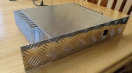
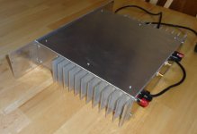
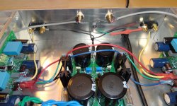
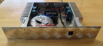
Finished the case.
Hi Guys,
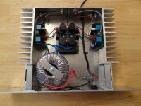
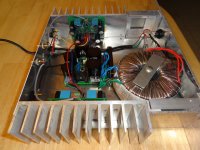
I built a case for this amp yesterday. Tried to fire it up last night through my light bulb tester and the light burned dimly so I shut it down and left it for this morning so I could check things out with fresh eyes. What I discovered was that with either channel powered separately, everything was fine, but with both channels powered, the bias would go from 145mA to 350mA. Both channels did the same thing. I had a very similar experience recently with my SKA. I had not installed a ground from the circuit to the case so I clamped a 10R 10w resistor from star to case and everything settled back to normal so I installed a 10R 1W resistor bypassed with two diodes and all is well. It sounds very very nice!
Hi Guys,
I built a case for this amp yesterday. Tried to fire it up last night through my light bulb tester and the light burned dimly so I shut it down and left it for this morning so I could check things out with fresh eyes. What I discovered was that with either channel powered separately, everything was fine, but with both channels powered, the bias would go from 145mA to 350mA. Both channels did the same thing. I had a very similar experience recently with my SKA. I had not installed a ground from the circuit to the case so I clamped a 10R 10w resistor from star to case and everything settled back to normal so I installed a 10R 1W resistor bypassed with two diodes and all is well. It sounds very very nice!
Attachments
- Home
- Amplifiers
- Solid State
- VSSA Through-Hole-PCB build thread