Normalized off,

Still doesn't look right.
The cyan (light blue) response is 30º and it does not look like the merged version.
Still doesn't look right.
The cyan (light blue) response is 30º and it does not look like the merged version.
It looks fine when I click the "axial" button for each response, but that doesn't seem to be what is being saved.
Axial response is "hor 0" which should be checked when exporting all responses with Export button.
One possible problem is DC offset either in reference channel with loop back or measurement/mic channel. Significantly too high level and response variation at low frequencies in several far field measurements indicate DC offset or environment noise. DC offset is quite unfortunate because dual channel mode is sensitive to it. 'Convert IR to FR' has compensation for DC offset which might reduce the problem, but it's not guaranteed.
Single channel mode is not so sensitive to DC offset, but has other problem: it cannot measure sound flying time i.e. time differences which is required for simulation up to 180 deg off-axis. But single channel mode is one method to test possible DC offset in reference channel.
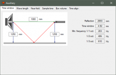
Time window should be short enough to block the first reflection which could cause level variation and directivity errors at LF.
One trick to reduce level variation is to use Hanning or Tukey 0.75 time window. Negative side effect compared to Tukey 0.25 is reduced resolution at LF.
I have CLIO which does not suffer this problem.
REW uses reference channel for timing reference, but does not manipulate measured response with reference channel. So REW could be better option than ARTA if sound card individual is not very good.
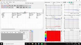
Important! First step after woofer measurements is to verify quality of far field responses. Load measured far field responses to empty project with single wire as a crossover and check how logical level at LF is 0-180 deg. Result doesn't have to be perfect to get acceptable power & DI result. In the best case normalized polarmap of 18" subwoofer looks something like this.
Attachments
Last edited:
Suddenly polar plot stopped working.
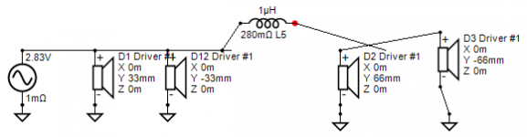
No it did not. Wiring of your crossover looks this so the last two drivers don't get any signal. Don't mess with wires. Don't add extra wires between components. That is just waste of time and increases risks to mess up whole network.
Drivers don't have off-axis responses so they are handled as omni. Show vertical to see lobing.
Attachments
Isn't it problematic in #2654 to turn the DUT when the distance to the mic is so long and the room so asymmetric? if the speaker DI is to be captured that is...
//
//
^Room asymmetry is not a problem because all reflections should be gated anyway.
"Too long" measurement distance may require "too short" time window assuming that distance from DUT to floor and ceiling are limited constants. 1000 mm from baffle surface to mic (mentioned in measurement instructions) is logical compromise especially with SPL calibrated systems, though it's not necessarily perfect far field yet and time window cannot capture higher order diffractions.
"Too long" measurement distance may require "too short" time window assuming that distance from DUT to floor and ceiling are limited constants. 1000 mm from baffle surface to mic (mentioned in measurement instructions) is logical compromise especially with SPL calibrated systems, though it's not necessarily perfect far field yet and time window cannot capture higher order diffractions.
Attachments
Here is the DC offset of my amplifier,

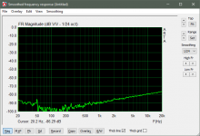
Here is Hanning window pir export, no merge, no XO.

Here is my setup,

I have a couple different amps I can try, a newer Gen 3 Focusrite Scarlett Solo and maybe shorter RCA's and speaker wires to see if that makes a difference.
These "flying tails" on the woofer response really mess things up...
David.
Here is Hanning window pir export, no merge, no XO.
Here is my setup,
I have a couple different amps I can try, a newer Gen 3 Focusrite Scarlett Solo and maybe shorter RCA's and speaker wires to see if that makes a difference.
These "flying tails" on the woofer response really mess things up...
David.
Last edited:
I would take reference signal from output of sound card i.e. semi-dual connection. Stable operation at LF is 100x more important than exactly accurate frequency response.
Another useful trick could be using Pink PN instead of sine sweep for woofer and mid. Looks that is gives more stable zero to IR than sweep at least with my Scarlett 2i2 2nd gen.
Mic disconnected, phantom power on, loop back from sound card i.e. semi-dual. Input pot at ~7/10:
Mic disconnected, phantom power on, loop back from sound card i.e. semi-dual. Input pot at ~7/10:
Attachments
Last edited:
Another useful trick could be using Pink PN instead of sine sweep for woofer and mid. Looks that is gives more stable zero to IR than sweep at least with my Scarlett 2i2 2nd gen.
Mic disconnected, phantom power on, loop back from sound card i.e. semi-dual. Input pot at ~7/10:
Since you mentioned it was a DC Offset problem, I noticed there was a DC offset button and clicked it, all is good now. 🙂

^Excellent. Next step is to include 100-180 deg measurements and fix sound balance which is not yet ok at least for far field speaker. Show In-room response and Total ER response in Power & DI graph and redesign balancing so that all visible traces are balanced without significant S-curve.
^Excellent. Next step is to include 100-180 deg measurements and fix sound balance which is not yet ok at least for far field speaker. Show In-room response and Total ER response in Power & DI graph and redesign balancing so that all visible traces are balanced without significant S-curve.
Can you explain more "Sound Balance"? (Power response, in room response?)
The drivers in the speaker are quite cheap (Dayton DA175-8 & Seas 27TFF, under $150 USD), so I don't want to get carried away with a super complicated/expensive crossover for this speaker. I went with this combo because the DA-175 works well sealed and I have a bunch of 27TFF.
This was really to have a speaker that was easy to measure (sealed) to test out the new measurement hardware and learn your software 🙂 .
I don't think there is a simple way to remove the "S" curves from the response.
If anyone wants to take a crack at an XO I can post the files.
Thanks for your help and Excellent Software!
^Loudspeaker, room and listener comprise a system, functioning together. What we finally hear is complex combination of direct sound and reflections. "Balanced sound" during simulation is just prediction of tonal quality with some assumptions about environment (and listener). So "sound balance" was subjective prediction of tonal balance according simulation.
Toole specifies few important frequency responses: on-axis, listening window, early reflections and sound power. Estimated in-room response is weighted average of listening window, early reflections and sound power. Those responses should be smooth without steps, S-curves or too steep tilt at HF.
Significance of each response depends on speaker concept, environment and setup/locations (and listener). For example sound power is the most significant response with omni speaker at far field in typical listening room.
In practice, early reflections is usually okay if sound power is okay so thumb rule is to optimize listening window and sound power, and fine tune with early reflections and estimated in-room response. Designer should not forget non-linear distortions, impedance, excessive overlapping of ways, individual on/off-axis responses etc.
Whole purpose of VituixCAD is to give previous information about directivity that designer is not forced to design by on-axis only. That is probably bad decision. On-axis should be good of course, but designer has information and possibilities to smooth other responses too or at least make much better compromise than "perfectly flat on-axis but everything else is crap".
7" alu woofer is not the best starting point but you should try.
Back to turntable. Main idea of rotating table is to measure off-axis responses that we could simulate crossover with measurement data to (quasi) full space. If crossover is designed by on-axis only, there's not so much sense to build whole thing, and simulator can be any simple and limited on-axis tool such as PCD or XSim. No need to mess with VituixCAD at all if goal is to design as blind.
Of course rotating table would be available for testing wave guide, horn and baffle prototypes, but that should happen before building enclosure because directivity of single radiator should be compatible with other radiators and estimated crossover frequencies and orders. Crossover is one of directivity components - part of the puzzle which tries to adapt other components together to produce "balanced sound".
Proper design order - if drivers are already selected - is to design shape of enclosure to support directivity features of drivers with estimated crossover frequencies and orders.
Unfortunately standard box about 200x350 mm is almost the worst case for hard cone 6.5" woofer and normal tweeter without wave guide with ~2 kHz XO because directivity of diffraction makes things worse: increases directivity of tweeter at XO, and decreases above XO. Baffle shape should decrease directivity at XO and below, and increase 1/2...1 octs above XO to smooth total directivity. That is not so easy without small flange tweeter because acoustical dimensions of baffle close to tweeter should be short in order to move S-curve to significantly higher frequencies. Another trick is to make front baffle twice bigger and add long rounding to prevent fragmentation of sound stage.
Last edited:
And finally, how to smooth directivity of 2-way with crossover. These are general tips - not necessarily possible, needed or the best. First forget very long traditions and false news on discussion forums that on-axis alone rules and crossover is not a directivity component.
1) Higher crossover frequency, shallower low pass of woofer and phase match above XO frequency increase directivity i.e. decrease power hump above crossover frequency. Additional filter order for treble cleaning can be added above acoustical XO frequency producing elliptical slope.
2) Shallower high pass of tweeter and phase mismatch below XO frequency decrease directivity i.e. decrease shallow power dip below crossover frequency. Additional filter order for tweeter protection can be added below XO frequency producing elliptical slope, or series LCR shunt at tweeter's fs to enable/help 1st order electrical high-pass.
3) Fine tune compromise between on-axis and off-axis (=early reflections, in-room and power) by increasing on-axis level below and at XO frequency and decreasing on-axis level at ~1 octave above XO frequency with shallow dip. Optimizer can do this automatically by weighting axial and power responses 40-60% ... 60-40%.
Very complex crossover indicates very optimized on-axis response which increases risk of poor directivity so the first step is to remove almost all components and restart schematic by monitoring both on-axis and off-axis (power etc). Nothing should be added for on-axis only if that makes off-axis and power significantly worse.

Could you show an example of this in the picture?Another trick is to make front baffle twice bigger and add long rounding to prevent fragmentation of sound stage.
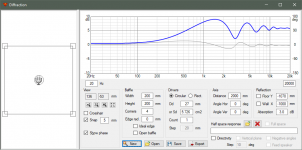
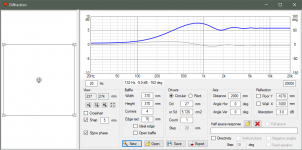
^Diffraction simulations are easier.
First one is close to worst case 200x200 R0 edges. Second one is 370x370 R70 edges. The last one is more compatible with 2-way crossed at ~1800 Hz because directivity index due to diffraction decreases from mid towards XO frequency while combination of hard cone and phase matched crossover reacts opposite.
First one is close to worst case 200x200 R0 edges. Second one is 370x370 R70 edges. The last one is more compatible with 2-way crossed at ~1800 Hz because directivity index due to diffraction decreases from mid towards XO frequency while combination of hard cone and phase matched crossover reacts opposite.
Attachments
- Home
- Design & Build
- Software Tools
- VituixCAD