Hi kimmosto/all
I have a question. I currently use VituixCAD to post process my FEM/BEM simulations (I export the frequency and phase response horizontally and verticalle and open them in VituixCAD). To save on computation time I only simulate the woofer to around 100 Hz( it is till a trail later this will go to 500 Hz) but when I import the responses, the Interpolation of the data does this:

Is there a way to adjust that or do I have to manipulate my data in order to avoid it?
Also, thanks for this amazing Software!
I have a question. I currently use VituixCAD to post process my FEM/BEM simulations (I export the frequency and phase response horizontally and verticalle and open them in VituixCAD). To save on computation time I only simulate the woofer to around 100 Hz( it is till a trail later this will go to 500 Hz) but when I import the responses, the Interpolation of the data does this:
Is there a way to adjust that or do I have to manipulate my data in order to avoid it?
Also, thanks for this amazing Software!
I figured out the different display of the measured and minimum phase in VituixCad2 and REW. The point is in the Z offset (drivers tab, at the bottom). When importing responses into VCad IR, Z is always = 0. In my case, I needed to make it = 7 mm. Then the phase and the minimum phase were displayed the same in both programs. Although there is a slight difference. About 5-10 degrees at the end of the range.
Is there a way to adjust that or do I have to manipulate my data in order to avoid it?
Slope detection and extrapolation is on by default so extra row e.g. 40 kHz added with text editor is only option at the moment. One octave above the highest existing is adequate in practice.
I just made cheap trick to revision 2.0.61.1 build 2021-02-05 which limits slope detection:
- maximum slope of frequency response extension is 0 dB/oct at HF
- minimum slope of impedance response extension is 0 "Ohms/oct" at LF
No need to edit manually if max. 0 dB/oct. extension is okay.
- maximum slope of frequency response extension is 0 dB/oct at HF
- minimum slope of impedance response extension is 0 "Ohms/oct" at LF
No need to edit manually if max. 0 dB/oct. extension is okay.
Last edited:
2.0.61.2 (2021-02-05)
* Code obfuscation settings changed to avoid false alarms from Symantec/Norton, Cynet and eGambit virus scanners.
* Added slope limits to response file reader. Maximum slope of frequency response extension is 0 dB/oct at HF. Minimum slope of impedance response extension is 0 ohm/oct at LF.
* Code obfuscation settings changed to avoid false alarms from Symantec/Norton, Cynet and eGambit virus scanners.
* Added slope limits to response file reader. Maximum slope of frequency response extension is 0 dB/oct at HF. Minimum slope of impedance response extension is 0 ohm/oct at LF.
7" alu woofer is not the best starting point but you should try.
How is this response?

Unusual reverse null,

Prior to the turntable and using your software I would have probably gone with this response because of the great reverse null,


Not knowing what the in room and power response was.
Keep in mind these drivers and this speaker build is/was just for learning and to test out my new finally completed measurement setup. I had never used ARTA before, I built a small amp that I can move outdoors with the rig in the summer, new ARTA turntable and ARTA box which I had never been tested. If I was going to wreck something, these drivers wouldn't matter.
Problem is, while I was getting the rig together, I ended up making a nice housing for this speaker, so I think I am going finish it.


Thank you,
David
^Axial response has still all the weight i.e. is too flat and tiny dips and humps are not necessarily in the best positions. So power response and other off-axis are still unbalanced.
Post #2676 tried to explain how to optimize both axial and power/off-axis to make working compromise so that over-optimized axial won't ruin the others. It's not very detailed, and perfect result is usually not possible. This would be easier to show with some project, but unfortunately I can't use my commercial projects.
In addition, reverse null doesn't have to be perfect and symmetrical. Controlled phase mismatch -> match over XO is able balance power on both sides of XO. Also turning of main beam a bit up is possible if slight mismatch is allowed.
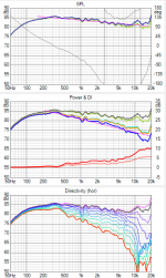
Ok. Two prototypes with Purifi 6.5" and TW030/AMT25 tweeter so not entirely compatible with Alu + 1" dome. Both phase matching acoustical 4th order. Some diffraction and directivity control with box shaping, and compromised axial to get decent overall balance. Not qualified for production but not due to sound balance.
Attachments
It is not my aim to start a flame war. But obviously I must be completely blind, because -in all fairness- I do not see a lot of difference between the first iteration of DaveFred and the Purify.
I am not implying this is a "good example" the way Dave asked, but here it is anyway, sharing with you. Designed with V2 and ARTA measurements. Following Kimmo's advices to the best of my knowledge.
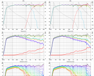
This is an actual measurement @ 1 m, tweeter axis, 0-90 hor, gated.
SB17NBAC04 + XT25/WG148, closed box, radiused edges r25 mm.
This is an actual measurement @ 1 m, tweeter axis, 0-90 hor, gated.
SB17NBAC04 + XT25/WG148, closed box, radiused edges r25 mm.
Attachments
But obviously I must be completely blind
🙂 I believe that you can see clearly. Only obvious thing by looking diyaudio and measurements of commercial speakers is that most of us and other speaker designers are not aware how CTA-2034-A traces should look. Almost without exceptions beginners with VituixCAD design exactly as bad as with XSim and other single...few response tools. It's mentally almost impossible to get rid of traditions of four...five decades and refuse illogicalities such as rising power and ED from XO frequency to octave above and e.g. accept compromise having tiny shallow hump below and tiny shallow dip above XO on-axis or play with phase mismatch below (but not above) XO.
Crossover cannot fix everything so shape and location of drivers including c-c should support smooth total directivity index in order to avoid compromises between on- and off-axis.
No dispute here about the necessity to optimize the Power Reponse as well: I fully agree.
But taking any design really to the next level requires quite a bit more work than x/o optimization with 36+1 measurements: your enclosure shape, more specifically baffle shape, should then also be optimized by using e.g. ABEC, COMSOL.
The impact of speaker placement on the baffle, baffle roundover and width, shape, waveguide/horn profile is profound. Just look at the tremendous efforts of Mabat, DonVK and Fluid in their respective threads. Optimizing what are still basically varieties of the a shoebox or monkey coffins remains sub-optimal i.m.o.
^Few message ago I just mentioned that shape should be smarter than shoe box or monkey coffin to avoid compromise where directivity index response is too twisted to be fixed with crossover alone. Smarter shaping does not necessarily require wavefront simulation with direct radiators though some knowledge and experience is needed. For example I don't need (and won't use) wavefront simulator for direct radiators to get responses logical enough for the crossover and listeners/customers.
Wave guides and horns might be different story, but Dave's case is not WG and I don't prefer those concepts.
Wave guides and horns might be different story, but Dave's case is not WG and I don't prefer those concepts.
One tiny thing. Too large wave guide causes dip to power at XO frequency. For example thumb rule that diameter of wave guide should be equal to woofer cone is probably bad idea no matter how brilliant wavefront it produces. Whole construction including components should be in balance as well as environment.
Here you raise a very interesting point. Would you recommend an oval waveguide or DXT type tweeter then?
As I see it, the sheer presence of any waveguide on a baffle disrupts the already unhappy physical shape/profile (cone/surround/frame) of the midwoofer further.
This looks like another case of picking your poison.
As I see it, the sheer presence of any waveguide on a baffle disrupts the already unhappy physical shape/profile (cone/surround/frame) of the midwoofer further.
This looks like another case of picking your poison.
- Home
- Design & Build
- Software Tools
- VituixCAD