Hi Kimmosto:
I have 12 rectangular slots placed on a circle like a clock face so D1 is at 1 oclock, D2 is at 2 oclock, etc. I defined and created directivity for the slot standing tall so the slots at 3 and 9 oclock have 0 degrees rotation and slots at 6 and 12 oclock have 90 degrees rotation. MY question is which way is rotation defined? For example is the slot at 2 oclock rotated -30 degrees? I'm guessing 2 o'clock is -30...clockwise is positive
Thanks,
Jack
^^At the moment I'm too shy and hesitant to recommend anything for wave guides and horns. Quite many years since I've had dome with wave guide or compression driver with horn. Mostly bad memories; prickly sound and very unbalanced compression spectrum especially with Al horns and Ti drivers. Blood flow from ears.
DXT had quite low acoustic resolution though room acoustics was terrible while testing that. Seas 27TB* with wave guide has been disappointment so I'm not very optimistic.
I try to play with plain (possibly diffused) Al/Be tweeters in shaped enclosures which are able too keep resolution, compression and projection spectrum balanced. Plastic compression driver in short horn of PA coax is also okay. Much less blood from ears. This approach kinda forces focus to room acoustics instead of excessive directivity at upper mid...mid treble. Combination produces natural balance in "everything" and enjoyable/relaxing reproduction imo. I don't design speakers for myself anymore, but personal preferences guide/limit commercial production.
Kimmosto, have you been able to determine a sort of "house directivity index curve/power response" you personally favor, that does not make your ears bleed?
^Power/DI tilt of 1.3 dB/oct from 150 Hz to 15 kHz is quite safe with flat on-axis or very small e.g. 0.05 dB/oct tilt down above 2 kHz. So maximum DI at 20 kHz would be 10...12 dB with conventional simple box speakers having omni LF.
Tilt of 1.5-1.6 dB/oct works too, but quality requirements for drivers increase due to more direct shooting/spitting to face.
Anyway quality of driver is more important than any certain power/DI tilt.
Tilt of 1.5-1.6 dB/oct works too, but quality requirements for drivers increase due to more direct shooting/spitting to face.
Anyway quality of driver is more important than any certain power/DI tilt.
A couple of questions for Draki (posts #2711 and #2713):
- I thought that any LR4 response using separate drivers (not a coax) would have a power response dip at the crossover point. My understanding this is a result from the LR crossover being a constant voltage vs a constant power type. So either my understanding is wrong or your crossover response doesn’t exactly follow a textbook LR24 response.
- Do you have a thread on that build?
Hi ErnPerkins
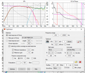
The system ended with almost textbook LR4, see attached target curves for both BM and the tweeter.
But I was not chasing it, it just happened to be LR24. Frankly, I am trying not to have a textbook target during design, nor a theoretical one, I find it distracting. Just keep "massaging" the xo while keeping an eye to the SPLFR, Power and DI.
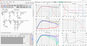
Attached is a final xo version and the predicted simulated responses. Of course different (better) results are very probably possible, this is where I stopped.
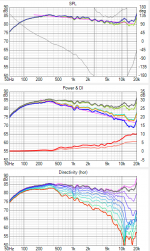
The actual measurement was posted earlier but I am posting it here again for an easier comparison. I had the speaker and mic left at the same position for a week (!) so they - the measurements - are under same conditions.
The system ended with almost textbook LR4, see attached target curves for both BM and the tweeter.
But I was not chasing it, it just happened to be LR24. Frankly, I am trying not to have a textbook target during design, nor a theoretical one, I find it distracting. Just keep "massaging" the xo while keeping an eye to the SPLFR, Power and DI.
Attached is a final xo version and the predicted simulated responses. Of course different (better) results are very probably possible, this is where I stopped.
The actual measurement was posted earlier but I am posting it here again for an easier comparison. I had the speaker and mic left at the same position for a week (!) so they - the measurements - are under same conditions.
Attachments

I think he's omitting the vertical plane in his measurements, thus you don't see the dip in the power response.A couple of questions for Draki (posts #2711 and #2713):
- I thought that any LR4 response using separate drivers (not a coax) would have a power response dip at the crossover point. My understanding this is a result from the LR crossover being a constant voltage vs a constant power type. So either my understanding is wrong or your crossover response doesn’t exactly follow a textbook LR24 response.
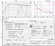
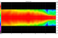
I didn't measure vertical. but here is the simulation: the dip is there big time, yes.
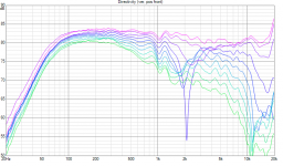
Also including hor polar (normalized)
Also including hor polar (normalized)
Attachments
Last edited:
which way is rotation defined?
Main program does not support simulated rotation of single driver instance around it's main axis (Z) so you cannot do this without creating response data with axis rotation of 30 and 60 degrees.
R parameter of driver instance is rotation around driver's vertical (Y) axis, and T parameter is rotation around horizontal (X) axis.
Simulated rotation and tilt produces inaccurate interpolated responses to quite many directions because response data in two planes only does not cover all possible off-axis angles. Balloon data is needed to improve accuracy, but VituixCAD does not support full balloon data.
This means that all drivers of complex speaker with significantly rotated drivers should be measured in large anechoic at listening distance and speaker should rotate around common origin while off-axis measurement sequences to get proper result with VCAD.
Draki, the influence of vertical measurements is applied by Y coordination of SB17 driver, in your case. Vituix just "borrowed" them from horizontals. It is clearly visible on DI at 2kHz, that bump is the result of the dip vertical off axis.
Petr, yes you are right of course. Warts and all....
Though I am more for the bottom line: it has to be finished at some point, objectively measure as good as the designer is willing and capable to make within various limitations, and at the end of the day, also subjectively sound good because that is why we are all into this hobby (except those who are professionals and may design to a customers specific needs/requests).
Kimmo, sorry if this turned OT.
I think he's omitting the vertical plane in his measurements, thus you don't see the dip in the power response.
That's definitely it! Makes sense now.
Emperkins, verticals are there, explained in my previous post. Careful eye would notice DI bump at 2kHz, which is usually sign that some sort of vertical measurements were included. Power response dip is not visible, the acoustic responses are not textbook LR24 responses, most probably, which is not a problem.
That's definitely it! Makes sense now.
Last edited:
^^No. Speakers are something else than two identical radiators with constant (flat) directivity and c-c equals to half wave length at XO frequency so power dip at XO does not necessarily exist. Flat axial and smooth power is fully possible with phase matching 4th order acoustical slopes, but requires good luck or controlled design of box shape, c-c distance, directivity of radiators ~size of cones and proper crossover design.
For example my sample with AMT25 (right side) has both horizontal and vertical response data for rectangular AMT tweeter. S-curve in DI response is less than 1 dB so DI response does not cause any compensation to axial response above XO frequency. Just tiny hump below XO to hide step in power response.
sorry if this turned OT.
That's perfectly fine because whole existence of VituixCAD is based on requirement to design also crossover with quasi full space response data. Limited data, methods, tools and knowledge about XO design could be the most common reasons why both diy and commercial designs have quite much variance and errors in very basic features such as tonal balance and tolerance for different listening environments and music genres.
It's also delightful to see that at least one person (outside Finland) is able to use recommended measurement and data processing methods and simulator properly. Few e-mails was also needed, but that's okay 🙂
Few e-mails was also needed
This is a gross understatement!
You have nerves of steel 🙂
Emperkins, verticals are there, explained in my previous post. Careful eye would notice DI bump at 2kHz, which is usually sign that some sort of vertical measurements were included. Power response dip is not visible, the acoustic responses are not textbook LR24 responses, most probably, which is not a problem.
I must be missing something. Here’s Draki’s DI plot from post #2711. I just don’t see a bump at 2 KHz.
Attachments
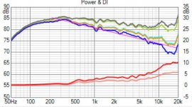
I see, I was looking at Draki #2726, there are 4 images, I refered to the second one (attached). The first one has flat DI at 2kHz as in #2711.
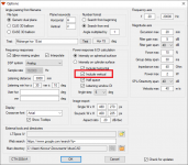
Draki, I think for the first one verticals were OFF (probably just measured horizontals of final complete loudspeaker), for the second one verticals ON (crossover modelling with individual driver horizontal responses). Am I correct?
Draki, I think for the first one verticals were OFF (probably just measured horizontals of final complete loudspeaker), for the second one verticals ON (crossover modelling with individual driver horizontal responses). Am I correct?
Attachments
Last edited:
For both - the system measurement and the simulation - the Option had both hor and ver active.
Just to be clear 100%:
- the simulation was made with 0-90 deg hor measurement at each DUT individual axis (x,y,z =0 for each)
- the system measurement was made 0-90 hor at the tweeter axis (thus making bass/mid at y -160 mm)
- both at 1000 mm distance to the mic
Just to be clear 100%:
- the simulation was made with 0-90 deg hor measurement at each DUT individual axis (x,y,z =0 for each)
- the system measurement was made 0-90 hor at the tweeter axis (thus making bass/mid at y -160 mm)
- both at 1000 mm distance to the mic
Last edited:
- Home
- Design & Build
- Software Tools
- VituixCAD