I am with Aksa and Prasi - beautiful layout Thiagomogi! The on board fat caps have their place in designs where we may not want to have a separate PSU board to clutter things up - such as when using a compact SMPS. This way, everything is off the floor and mounted on the side walls where the big heatsink is.
Have you posted Gerbers for this yet?
Thanks!
@Aksa - thanks for the kind words - it's great to learn from the Masters on this forum.
Have you posted Gerbers for this yet?
Thanks!
@Aksa - thanks for the kind words - it's great to learn from the Masters on this forum.
I am with Aksa and Prasi - beautiful layout Thiagomogi! The on board fat caps have their place in designs where we may not want to have a separate PSU board to clutter things up - such as when using a compact SMPS. This way, everything is off the floor and mounted on the side walls where the big heatsink is.
Have you posted Gerbers for this yet?
Thanks!
@Aksa - thanks for the kind words - it's great to learn from the Masters on this forum.
Thanks guys .
All I know I owe to this forum , so I'm happy to be helpful.
Gerber files attached would be happy to see built.
166x75mm size
Best Regards
Attachments
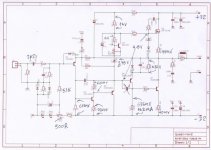
Total collector current from the inverter transistor might be 8.5mAYes, Thimios, but you need to ensure that when you set the appropriate quiescent (somewhere between 100mA and 140mA, as you wish) at idle there is:
1. majority of current is passed through the Baxandall 100R resistor, and
2. a small current is passed through the Baxandall diode.
This removes the diode switching from the full waveform since the Bax diode is always ON.
This fine detail leverages the benefits of this network. To give you some idea:
Total collector current from the inverter transistor might be 8.5mA
Current through resistor might be 6mA
Current through diode might be 2.5mA
Generally you need to make the Bax resistor much smaller than the base to negative rail resistor. 100R v. 150R is a good ratio assuming the beta of the quasi output device is at least 80.
Cheers,
Hugh
Current through resistor might be 6mA
Current through diode might be 2.5mA
Here is what i measure.I see 4.2mA collector current,do you see something wrong?
Attachments
Thimios,
All your voltages and currents look fine; only a polishing is needed!
1. I would suggest you straddle the Vbe multiplier and the zener with C7 (? - I am doing this on mobile phone lying in bed so can't easily check).
2. I estimate the quasi base is drawing 1.5mA so adding your measured 4.2mA we
have 5.7mA drawn through the phase inverter collector. You have 520mV across the Bax resistor and only 0.5mA drawn through the Bax diode.
When the nmos starts to switch on this diode will turn off swiftly and spray artefacts into the output node very close to the crossover point where discontinuities in the waveform are fatigueing. Solution: Increase the Bax resistor to 120 ohms.
Ciao
Hugh
Ok Hugh take your time,i will wait for all your suggestions when you are ready.Thimios,
All your voltages and currents look fine; only a polishing is needed!
1. I would suggest you straddle the Vbe multiplier and the zener with C7 (? - I am doing this on mobile phone lying in bed so can't easily check).
2. I estimate the quasi base is drawing 1.5mA so adding your measured 4.2mA we
have 5.7mA drawn through the phase inverter collector. You have 520mV across the Bax resistor and only 0.5mA drawn through the Bax diode.
When the nmos starts to switch on this diode will turn off swiftly and spray artefacts into the output node very close to the crossover point where discontinuities in the waveform are fatigueing. Solution: Increase the Bax resistor to 120 ohms.
Ciao
Hugh
Thanks.
The Bax diode may be passing virtually zero current if the 5200/Q7 gain/hFE is >120
Should R14 be reduced significantly below 150r?
Does the Bax diode need to be passing during the quiescent phase?
Does the Bax diode need to pass during all normal levels of output current?
Should R14 be reduced significantly below 150r?
Does the Bax diode need to be passing during the quiescent phase?
Does the Bax diode need to pass during all normal levels of output current?
Last edited:
Hi Guys
Mosfets tend to be more nonlinear at low idle currents, plus the circuit is highly asymmetric requiring higher idle to achieve reasonable performance.
Have fun
Thanks Kevin, I think You just answered my question. Im a happy owner of Your book, BTW(P of P)
Cheers
J.
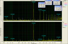
Yes, but it could easily be a minor issue with ground impedance too. Very critical to THD, but, and note this, YOUR EAR WON'T NOTICE!!
Sure i can't hear but i can see🙂🙂🙂
Finally it doesn't matter of gnd resistance.
Each channel tested alone with exactly the same configuration .
Why this difference?
Amplifier modules are the left channel when on the Right Channel is an input. out.sound card loop.
Sure i can't hear but i can see🙂🙂🙂
Finally it doesn't matter of gnd resistance.
Each channel tested alone with exactly the same configuration .
Why this difference?
Amplifier modules are the left channel when on the Right Channel is an input. out.sound card loop.
Attachments

Last edited:
Thimios,
If all the active parts are the same, and their betas and Vbe setting are the same, and input and output are identical there should be no difference in THD. We are down to lowish global negative feedback because of the nested fb resistor (68k) and therefore the THD will vary with unmatched parts.
However, you should hear no difference! What are your thoughts now you have a stereo system?
Cheers,
Hugh
Thanks Hugh,still working in amplifier polishing😉Thimios,
If all the active parts are the same, and their betas and Vbe setting are the same, and input and output are identical there should be no difference in THD. We are down to lowish global negative feedback because of the nested fb resistor (68k) and therefore the THD will vary with unmatched parts.
However, you should hear no difference! What are your thoughts now you have a stereo system?
Cheers,
Hugh
I think that is enough!Thimios,
Tell us how shiny it is now!
Hugh
This Weekend will come at home with me, for a mini blind test😀
Wow, I populated the boards yesterday but was having fits trying to get it working. Current was through the roof. This morning, laying in bed I noticed that D7 is a 3.3V Zener. I had a 1n4007 in there. I just checked my parts bin and the closest I have it 4.7V so I guess I'll have to place an order. Bummer.
Ask Hugh if two red leds in series will do the work.😉Wow, I populated the boards yesterday but was having fits trying to get it working. Current was through the roof. This morning, laying in bed I noticed that D7 is a 3.3V Zener. I had a 1n4007 in there. I just checked my parts bin and the closest I have it 4.7V so I guess I'll have to place an order. Bummer.
Andrew,
My apologies for slow response to your questions.
1. The Bax diode should be passing at less 1.5mA at quiescent. Reason is that while it turns on and off this transition should occura couple volts above crossover when the nmos is passing sufficient current to swamp the switching artefacts of the diode.
2. The Bax 22nF cap helps to squelch the switching noise as well.
3. When you examine the nmos current on LTSpice you notice that careful of Bax network, the quiescent current and the base to rail resistor and the nmos choice, you can keep the nmos ON and passing current across the FULL waveform!
The quasi does switch of course, but the nmos, which determines the voltage at its source stays on the full 360 degrees.
There are benefits for the quasi topology; it blurrs the classic crossover we see with the complementary OPS.
The asymmetrical treatment of the signal generates H2, H4 and H6 and most listeners perceive it as 'warm'
Hugh
Yes Terry two redleds (2 × 1.6V) will do fine and dandy!
The anode attaches to bottom of Vbe emitter and cathode attaches to anode of second redled.gest
You don't need to order!
Hugh
The anode attaches to bottom of Vbe emitter and cathode attaches to anode of second redled.gest
You don't need to order!
Hugh
Last edited:
Hi Hugh,
I installed a single blue LED and it is working perfectly. I had to install 100k for R5 in order to zero the offset with the 200R trimmer. I actually installed a 100k trimmer in place of R5 and centered VR1. I had the 100k maxed and it turned out to be about perfect so I just installed 100k resistors and now all is well. I have it running on +-44V right now because my variac went out last night. I will have to set up an adjustable PSU to do further testing because I don't have a 24-0-25vac transformer available right now. I can probably get by with the +-44V for some quick testing if I run it on 8 ohm speakers.
Stay tuned.
Blessings, Terry
Hi Hugh,
I installed a single blue LED and it is working perfectly. I had to install 100k for R5 in order to zero the offset with the 200R trimmer. I actually installed a 100k trimmer in place of R5 and centered VR1. I had the 100k maxed and it turned out to be about perfect so I just installed 100k resistors and now all is well. I have it running on +-44V right now because my variac went out last night. I will have to set up an adjustable PSU to do further testing because I don't have a 24-0-25vac transformer available right now. I can probably get by with the +-44V for some quick testing if I run it on 8 ohm speakers.
Stay tuned.
Blessings, Terry
looking forward to the test 😀
Terry, when you have the time look at this.Hi Hugh,
I installed a single blue LED and it is working perfectly. I had to install 100k for R5 in order to zero the offset with the 200R trimmer. I actually installed a 100k trimmer in place of R5 and centered VR1. I had the 100k maxed and it turned out to be about perfect so I just installed 100k resistors and now all is well. I have it running on +-44V right now because my variac went out last night. I will have to set up an adjustable PSU to do further testing because I don't have a 24-0-25vac transformer available right now. I can probably get by with the +-44V for some quick testing if I run it on 8 ohm speakers.
Stay tuned.
Blessings, Terry
I believe that is a good solution for your tests.http://www.diyaudio.com/forums/power-supplies/294017-controling-main-transformer.html#post4774973
looking forward to the test 😀
Yes.. You bet, I am waiting too. Now we have two pairs of ears to give glimpse of SQ.
- Home
- Amplifiers
- Solid State
- Very simple quasi complimentary MOSFET amplifier