It just depends on how much power supply ripple you are willing to tolerate. At some point, it has audible hum from the mains. 4 x 4700uF should be fine for many Class AB amps (as a speaker amp). I myself, just ordered 8 x 9600uF 50v caps from Mouser and they cost a pretty penny - the single biggest cost of this amp, aside from the CNC aluminum case.
Yes, thanks X, 42V
My future VSQ will be similar to post #1658, as my avaiable transformers will give supply about +-48Vdc. 😱
After a small trip to Portugal... 😎
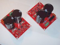
Attached the single channel supplies.
Regards.
Attachments
Last edited:
Yes, Meanman, 4,700uF would be fine as it's a Class AB and ripple requirements are not so strict as a Class A.....!
Hugh
Hugh
A quick update: The free PCB sets are all spoken for now, so no more PMs please.
Prasi> Yes I would be glad to send you a set. Just send me your address. Postage is on me 🙂
Prasi> Yes I would be glad to send you a set. Just send me your address. Postage is on me 🙂
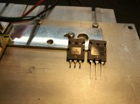
Hugh , you told us that we can use FQA40N25 fet, does it also need the cap-resistor combo between gate and drain as in the Naksa125 ?
Yes, Patrick.
These are high transconductance devices, and I use 220p and 47R in series across gate and drain. They are snubbers, and they damp out the oscillations which are common with high Gm mosfets, a Cordell trick from the eighties.
Ciao,
Hugh
These are high transconductance devices, and I use 220p and 47R in series across gate and drain. They are snubbers, and they damp out the oscillations which are common with high Gm mosfets, a Cordell trick from the eighties.
Ciao,
Hugh
Unfortunately I had a little mishap.😱I pulled the connector out of the signal generator while the amp were still powered. I suppose it caused a feedback or oscillation that killed both output devices on one module. Will have to source trannies for that. I found that the output is 100% with a square wave on 1khz but on 10khz there is a little overshoot and a notch. Any idea how to fix that ?
Attachments
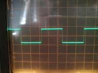
Ulp. You should never run an audio amp at 1KHz full power square wave. It is a destructive test, though you can do it for about two or three seconds.
Just replace the outputs and be aware this amp sounds just fine. Don't try to test it again; just listen to it Jan!
Cheers,
Hugh
Just replace the outputs and be aware this amp sounds just fine. Don't try to test it again; just listen to it Jan!
Cheers,
Hugh
I was also wondering about the schematic to this layout. Especial the power-section, one input and three rectifiers at each side ?
Can anyone please point me to the schematic?
And regarding the power supply for this application and in general. What about using a DC-DC converter instead of capacitance multiplier? Cheaper better?
Lydlaug
Can anyone please point me to the schematic?
And regarding the power supply for this application and in general. What about using a DC-DC converter instead of capacitance multiplier? Cheaper better?
Lydlaug
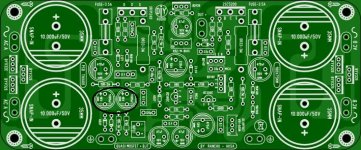
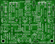
How critical is the value of these caps ?I mean the capacitance of the caps in the black circle the two 1000µF ones.
Attachments
Last edited:
I was also wondering about the schematic to this layout. Especial the power-section, one input and three rectifiers at each side ?
Can anyone please point me to the schematic?
And regarding the power supply for this application and in general. What about using a DC-DC converter instead of capacitance multiplier? Cheaper better?
Lydlaug
Yes, this circuit has a few departures from the basic quasi circuit we have all used up to this point from Christian and Hugh. I have never seen 3 diodes on a rectifier before. It would be good to have the final schematic corresponding to the board - I can't seem to find it either and I have the board in hand.
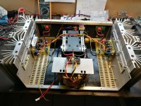
I have received the new MJL3281trannies. They do look a little different from my old one's. But they work well , got them from RS so should be original. Both channels running at +- 34mv bias and sounds superbb ! This would be be finished before x-mas for my daughter !! Thanks Hugh, Ranchu and all !!😀😀😀😀
Attachments
Meanman, Hugh suggested a 470uf for C4. So the 1000uf caps are not necessary all thou I used the 1000uf caps on Thiago's circuit. I believe these work for sure.🙂
Attachments
Last edited:
Yes, this circuit has a few departures from the basic quasi circuit we have all used up to this point from Christian and Hugh. I have never seen 3 diodes on a rectifier before. It would be good to have the final schematic corresponding to the board - I can't seem to find it either and I have the board in hand.
the rectification was suggested by Hugh, identical to the Aspen Fetzilla.
Attachments
How critical is the value of these caps ?I mean the capacitance of the caps in the black circle the two 1000µF ones.
who has followed the discussion from the beginning, knows which pieces may have changed the values to suit individual taste.
I like what the pcb looks like
Thiago
- Home
- Amplifiers
- Solid State
- Very simple quasi complimentary MOSFET amplifier