Have just desoldered and measured the left channel filter board caps and they were all fine.
Will now check C28 and C29 and the anode voltages as described.
Yes, such a relief to be this close today considering yesterday I was almost buying another FPGA.
Will now check C28 and C29 and the anode voltages as described.
Yes, such a relief to be this close today considering yesterday I was almost buying another FPGA.
C28 and C29 measured just fine...no shorts.
Anode voltages are as follows:
U1A -23
U1B -27
U2A -27
U2B -23
U28A -27
U28B -23
U30A -23
U30B -27
Anode voltages are as follows:
U1A -23
U1B -27
U2A -27
U2B -23
U28A -27
U28B -23
U30A -23
U30B -27
That's all good. Either one of the big DC blocking capacitors on the main board is not connected or there is a short or open somewhere in the left channel of the filter board then.
Have reflowed all the DC blocking caps along with all the inductor connections and nothing has changed. Measured the 1kHz going into the OPT's, as opposed to originally measuring at their output and nothing has changed, so the transformers seem to both be 1:1, which is good.
Measured at the DC blocking caps and the left channel measures about 4.5Vp-p and the right channel 4.0Vp-p so very similar there...the problem is definitely in between the DC Blocking caps on the main board and the OPT's on the filter board...just have to find it.
Measured at the DC blocking caps and the left channel measures about 4.5Vp-p and the right channel 4.0Vp-p so very similar there...the problem is definitely in between the DC Blocking caps on the main board and the OPT's on the filter board...just have to find it.
Got it!
Was an error of hindsight. Checked and rechecked everything on the filter board, was starting to pull my hair out, then I remembered Marcels advice about grounding the OPT secondaries...did that...volume problem is gone. Still a fair bit of noise in the left channel but tomorrow I will see if I can trim that out with the trimpot.
Sounds very promising...first thing is to sort out some noise.
Strange that you only had a factor of two difference between left and right then. Anyway, great that you have solved it!
Thanks so much for your help thus far Marcel, I could not have asked for more and to be honest this build has had quite a few new things for me including the digital stuff... those Hirose FPGA connectors are the devils work for a beginner and seem to have been the main issue for both Sonny and myself.
Not just for beginners; an ex-colleague of mine who worked in the lab and soldered SMDs at work as well as in his spare time also doesn't like them. It's a pity those modules don't come with something that's a bit easier to solder. I've seen Artix 7 modules with ordinary headers, but those have lousy grounding.
The trimpots can reduce the noise a lot. I also moved the tubes around until I got the quietest arrangement, though I'm not using "nice" tubes. Just some JAN Phillips
Got it!
Was an error of hindsight. Checked and rechecked everything on the filter board, was starting to pull my hair out, then I remembered Marcels advice about grounding the OPT secondaries...did that...volume problem is gone. Still a fair bit of noise in the left channel but tomorrow I will see if I can trim that out with the trimpot.
Sounds very promising...first thing is to sort out some noise.
Found a moment to adjust the trimpots in an attempt to cancel out the noise this morning and it quickly become apparent that the first thing to solve is a major hum issue at mains frequency 50Hz. It is quite loud and in both channels and appears right where it should in the middle of the soundstage which means there are a lot of harmonics involved. Will pull out the audio analyser and see what can be measured at the outputs.
Marcel, i meant ; "are they connected to anything" ... not on the drawing but actual wires..
I found that if i forgot to make that connection , leaving them floating will induce hum...
Could this be the case here?
I found that if i forgot to make that connection , leaving them floating will induce hum...
Could this be the case here?
It's certainly possible, but it doesn't seem likely, as it is a connection made by soldering through-hole components on a PCB. When you forget to populate both of the two 100 ohm resistors, then the heaters will float.
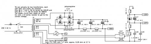
This may be paranoia, but would the inductance of wire-wound resistors cause issues if used in certain spots? I used them at R43, R44, R139, R140, and R141. I used metal oxide at R123 and R128. I used wire-wound because of the availability of higher wattage ratings.
I don't expect any issue due to resistor inductance at those locations. They are basically just handling DC and most of them have big decoupling capacitors across them (except R123, which is only involved in the neon lamp/LED driving part).
Found a moment to adjust the trimpots in an attempt to cancel out the noise this morning and it quickly become apparent that the first thing to solve is a major hum issue at mains frequency 50Hz. It is quite loud and in both channels and appears right where it should in the middle of the soundstage which means there are a lot of harmonics involved. Will pull out the audio analyser and see what can be measured at the outputs.
How many connections are there between the DAC ground and the amplifier ground? If there are none, neither via signal cables nor via protective earth, you could get pretty large 50 Hz common-mode voltages between the DAC and the amplifier and a bit of imbalance might then cause hum. If there are two or more and they enclose a large loop area, you have the classical hum loop.
Have found a few moments to look at the hum issue and it seems as though I can choose only one of two things:
(1) Loud 50Hz hum with equal output left and right channels
(2) No hum with one channel half the volume of the other
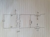
These two behaviours stem from where I choose to connect the OPT to ground on the filter board. If I use the middle of the secondary winding then it hums but both channels have the same output. If I connect from the -ve outputs of the secondary then no hum but channel imbalance.
In this case the resistor terminating the filter is not really necessary because the OPT primaries would present a 600R load to the Reconstruction Filter.
(1) Loud 50Hz hum with equal output left and right channels
(2) No hum with one channel half the volume of the other
These two behaviours stem from where I choose to connect the OPT to ground on the filter board. If I use the middle of the secondary winding then it hums but both channels have the same output. If I connect from the -ve outputs of the secondary then no hum but channel imbalance.
In this case the resistor terminating the filter is not really necessary because the OPT primaries would present a 600R load to the Reconstruction Filter.
Attachments
- Home
- Source & Line
- Digital Line Level
- Valve DAC from Linear Audio volume 13