How many connections are there between the DAC ground and the amplifier ground? If there are none, neither via signal cables nor via protective earth, you could get pretty large 50 Hz common-mode voltages between the DAC and the amplifier and a bit of imbalance might then cause hum. If there are two or more and they enclose a large loop area, you have the classical hum loop.
Dac and preamp are plugged into the same mains powerboard and the only other connection between the two are the RCA cables.
2) No hum with one channel half the volume of the other
Do both have a ground connection to your mains ground?
Do both have a ground connection to your mains ground?
Have found a few moments to look at the hum issue and it seems as though I can choose only one of two things:
(1) Loud 50Hz hum with equal output left and right channels
(2) No hum with one channel half the volume of the other
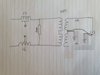
These two behaviours stem from where I choose to connect the OPT to ground on the filter board. If I use the middle of the secondary winding then it hums but both channels have the same output. If I connect from the -ve outputs of the secondary then no hum but channel imbalance.
Dac and preamp are plugged into the same mains powerboard and the only other connection between the two are the RCA cables.
In the case where the centre tap is connected, is the negative side of the secondary winding open? Or is the negative side connected via the signal cable and the centre tap via the protective earth, so the bottom half of the transformer's secondary gets shorted? In either case the effects you observe don't make sense to me yet.
You get channel imbalance when you use the complete secondary windings rather than the upper halves. Does that mean there is something wrong with the bottom half of the secondary winding of one of the transformers?
In this case the resistor terminating the filter is not really necessary because the OPT primaries would present a 600R load to the Reconstruction Filter.
How's that? Does your amplifier have a 600 ohm input impedance?
Attachments
Last edited:
Yes, I have done that previously, at the DC Blocking caps. The two channels were fairly close to each other in amplitude with a 1kHz sine.
2) No hum with one channel half the volume of the other
Do both have a ground connection to your mains ground?
This should be handled via the circuit boards and cable connections. Have not specifically tested this, but I do have the same voltages at the DC Blocking caps.
In the case where the centre tap is connected, is the negative side of the secondary winding open? Or is the negative side connected via the signal cable and the centre tap via the protective earth, so the bottom half of the transformer's secondary gets shorted? In either case the effects you observe don't make sense to me yet.
No change in wiring from my previous handwritten drawing apart from the connection to ground moving from the -ve end of the secondary winding to the centre-tap for both channels.
I should closely check the wiring of the OPT's to make sure they both actually comply to the diagram with which they arrived. It may be that simple.
How's that? Does your amplifier have a 600 ohm input impedance?
When used with both windings in series, the OPT primary has a DCR of 600ohm.
Regarding the impedance, what matters for the filter termination is the impedance at audio frequencies and around the filter cut-off frequency. Neglecting all second-order effects, that is determined by the impedance of whatever loads the secondary divided by the square of the voltage step-up ratio.
Taking into account wire resistance (but still neglecting skin effect, iron losses and a lot of other things), it's the DC resistance of the primary plus the sum of the secondary's DC resistance and the impedance of whatever loads the secondary divided by the square of the voltage step-up ratio, so Rdcprim + (Rdcsec + Zload)/n^2. With a step-up ratio of one, that's simply the impedance of the load plus the primary wire resistance plus the secondary wire resistance.
Taking into account wire resistance (but still neglecting skin effect, iron losses and a lot of other things), it's the DC resistance of the primary plus the sum of the secondary's DC resistance and the impedance of whatever loads the secondary divided by the square of the voltage step-up ratio, so Rdcprim + (Rdcsec + Zload)/n^2. With a step-up ratio of one, that's simply the impedance of the load plus the primary wire resistance plus the secondary wire resistance.
Ok. Have found some more time today to fault check my ValveDac. Left channel is obviously putting out less volume than the right.
Previously I had tested the OPT's for shorted windings, DCR, inductance and general function and they are both fine. No problem with the iron it seems.
One thing I did realise is that the old analogue oscilloscope may have developed a fault because it is giving me rubbish and varying readings so it is ditched for now. I do have quite a decent DMM which when used correlates to what I am hearing and measuring with the SPL Meter, which is that with a 1kHz sine playing the left channel outputs 162mVAC and the right 435mVac. The SPL meter is reading about 8dB difference at the mouth of the midrange horn between left and right channels. The measurement equipment seems to correlate so all good there.
Still using the DMM with the 1kHz sine playing through the speakers at the 600R resistors that terminate the reconstruction filters (so at the input to the OPT's) I am reading a little more than what comes out of each OPT so there is a small loss in each OPT that is to be expected. Still all good.
Move the DMM back to the DC Blocking caps while still playing the 1kHz sine through the speakers and for the right channel I measure 535mVAC (all good) but the left channel is over 12VAC...yes volts...between C31 and C32. Gave RV1 a spin for a while and the voltage did not change nor did it when tubes were swapped.
With the filter board disconnected there is about 15VAC across both C32/C31 and C54/C53, so by my thinking the problem is somewhere on the filter board between the pcb input and OPT input...all those inductors and caps in the left channel, but I cannot find the problem. It's driving me nuts especially with all the confusing readings the oscilloscope was giving before I set it aside.
It seems there must be an open connection somewhere, the signal level from the main board always increases a lot (as does the noise modulation) when one or both sides of an output of the main board isn't loaded by the filter. As the readings change in ways that don't make sense, maybe it's an intermittent contact somewhere.
Besides the filter board inductors, transformer or connections between them, it could also be the cable from the main board to the filter board. I don't see how a filter board capacitor failure could cause this, so they are in the clear as far as I'm concerned.
Besides the filter board inductors, transformer or connections between them, it could also be the cable from the main board to the filter board. I don't see how a filter board capacitor failure could cause this, so they are in the clear as far as I'm concerned.
Last edited:
Just calculated out the OPT insertion loss and it is about 1.7dB for both channels.
Have checked all the +ve and -ve contacts for each line on the filter board and they all measure 0.1R to 0.3R from start to finish and about 54R from +ve to -ve (OPT primary measures DCR 60R and I'm using a 604R at termination of each filter...parallel 54R) at all points of each channel. No caps are shorted, all inductor casings are well connected to ground.
Will check the cable and connections...have not previously done so.
One thing I have been thinking about is the termination impedance of the Reconstruction Filter and the difference between the Jensen OPT and the Slagle that I am using. Basic specs:
DCR Pri. DCR Sec. Insertion Loss
Jensen 39R 112R 1.9dB
Slagle 60R 78R 1.7dB
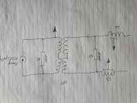
Based on those DCR specs the transformers either have a different turns ratio or the Jensen uses much finer wire for secondaries than the primaries (hence the higher DCR), which may or may not affect the turns ratio. Both are 1:1 transformers and I'm no expert here, but perhaps the Reconstruction Filter could be seeing too low a termination impedance with the Slagle OPT and the right channel has just enough "drive" to get over it but the left channel is suffering hence the lower output. See the attached diagram for how things are currently wired.
My rough calcs are that the OPT secondaries are loaded to about 596R (47kR and 604R in parallel), then the turns ratio across the OPT which should be about unity but may be different between the Slagle and Jensen units, then the 604R R1 in parallel again give 300R filter termination load. Maybe I should get rid of R1 and see what happens?
Wired as is there is literally zero noise with my head in any of the horns. The ValveDac is connected to a pre with fixed 8x gain and autoformer volume control at output and the horns are 110dB/w/m sensitive...nothing but silence...I love it...hopefully this remains with the final solution for these issues.
Have checked all the +ve and -ve contacts for each line on the filter board and they all measure 0.1R to 0.3R from start to finish and about 54R from +ve to -ve (OPT primary measures DCR 60R and I'm using a 604R at termination of each filter...parallel 54R) at all points of each channel. No caps are shorted, all inductor casings are well connected to ground.
Will check the cable and connections...have not previously done so.
One thing I have been thinking about is the termination impedance of the Reconstruction Filter and the difference between the Jensen OPT and the Slagle that I am using. Basic specs:
DCR Pri. DCR Sec. Insertion Loss
Jensen 39R 112R 1.9dB
Slagle 60R 78R 1.7dB
Based on those DCR specs the transformers either have a different turns ratio or the Jensen uses much finer wire for secondaries than the primaries (hence the higher DCR), which may or may not affect the turns ratio. Both are 1:1 transformers and I'm no expert here, but perhaps the Reconstruction Filter could be seeing too low a termination impedance with the Slagle OPT and the right channel has just enough "drive" to get over it but the left channel is suffering hence the lower output. See the attached diagram for how things are currently wired.
My rough calcs are that the OPT secondaries are loaded to about 596R (47kR and 604R in parallel), then the turns ratio across the OPT which should be about unity but may be different between the Slagle and Jensen units, then the 604R R1 in parallel again give 300R filter termination load. Maybe I should get rid of R1 and see what happens?
Wired as is there is literally zero noise with my head in any of the horns. The ValveDac is connected to a pre with fixed 8x gain and autoformer volume control at output and the horns are 110dB/w/m sensitive...nothing but silence...I love it...hopefully this remains with the final solution for these issues.
Attachments
If you switch the conections between the DAC and filter boards does the left channel become good and the right not? I know it's really basic but it would at least confirm the problem as being in just one half of the output filter PCB - if that's the case the end of your journey must be very close.
Good luck
Good luck
Here is a new one. The filter-to-dac cable can only be checked with power on because the relays short signal to ground unless the relay is opened by the dac logic. So, poking around on there with the power on and everything connected I am getting exactly the resistance readings that I should be i.e. nothing connects to ground that should not and nothing is different to testing the filter board when it is unplugged from the dac board.
What is different though, is that with nothing playing there is sub mVAC between DC Blocking Caps C31/C32 but put on the 1kHz sines and we have more than 12vAC...with music it jumps around a lot but the Fluke 287 still shows values measured in multiple vAC rather than mVac like the other channel (that works properly).
nautibuoy, it is not simple to just swap channels, but I think I should give it a go.
The filter termination resistance is indeed about 300 ohm now, which more or less halves the output signal level and can cause some abberations in the frequency response, particularly in the ultrasonic region. It can't explain the issue you have, though.
I think I will remove that resistor. Have been aiming for 600r filter load to get the output I think I need...which is pretty close to what it is now, but not quite.
Made up a cable to swap channels on the filter pcb. The ValveDac LHS now drives the RHS filter, and so on. Also removed R1 on my previous sketch so should be getting roughly double the output voltage previously.
Results:
(1) low output has shifted from left speaker to right speaker and high output from right to left
(2) High output is 0.94Vac...was previously about half that...so this is correct
(3) Low output is still 0.16V...has not doubled and is exactly the same as before other than now being on the opposite speaker.
(4) Still have more than 12Vac between the DC Blocking Caps C32/C31
Am thinking now that the issue is on the dac pcb.
Maybe there is some DC leaking in one of the DC blocking capacitors? Maybe the DVM reads the overlaying DC as well?
I think I will remove that resistor. Have been aiming for 600r filter load to get the output I think I need...which is pretty close to what it is now, but not quite.
I’ve been reading this thread for quite a while with great interest.
My two cents, buy a decent Picoscope, the best investment you can make to analyse analog and digital signals.
For such a complex project you can hardly do without.
Hans
Not familiar with the Picoscope, but I do have an RTX6001 and MIpro full license but have not had time to get familiar with it. Don't even know if the Tek probes can be used with it. I'm in agriculture, not electronics, and am doing my best here but need a bit of hand holding for this digital stuff.
- Home
- Source & Line
- Digital Line Level
- Valve DAC from Linear Audio volume 13