java tools paint_kit.jar for triode, paint_kip.jar for pentode.I see that folks here appear to use a program to graphically fit the IV curve images from data sheets.
Does this program have a name and is it available as open source?
There are currently 197 pages to this thread and it is quite the thing to sort through!
www.dmitrynizh.com/tubeparams_image.htm
requires java to be installed on your computer to work
You can restrict the search tool to search just the model thread rather than the whole forum.
Go to the model thread, enter the tube designation you are looking for into the search window and select 'search this thread only'
Last edited:
Thank you rongon!
I tried to cross reference the 6J5GT to identify a relevant model using this tube substitution source - https://www.worldradiohistory.com/B...ks/SAMS-Tube-Substitution-Handbook-Vol.-7.pdf
It did not provide a reference to a 6SN7.
How did you determine that that model was usable?
I tried to cross reference the 6J5GT to identify a relevant model using this tube substitution source - https://www.worldradiohistory.com/B...ks/SAMS-Tube-Substitution-Handbook-Vol.-7.pdf
It did not provide a reference to a 6SN7.
How did you determine that that model was usable?
Thank you Sorento!
I will have a look at this and see if I can make use of it for my needs.
The CK6419 that I am interested in modeling uses a combined heater/cathode configuration.
Does anyone know of any previous efforts to model such a structure that includes this sort of structure?
I will have a look at this and see if I can make use of it for my needs.
The CK6419 that I am interested in modeling uses a combined heater/cathode configuration.
Does anyone know of any previous efforts to model such a structure that includes this sort of structure?
What you call "a combined heater/cathode configuration" is usually referred to as a DHT (Directly Heated Tube).
As opposed to Indirect Heating.
DHT is how it all began with vacuum tubes. The filament =is= the cathode.
In the beginning the filaments were run as hot as in an incandescent light bulb.
Later and up to the present the filament was coated with barium oxide or so to allow effective emission at lower temperatures.
In your case of the CK6419 - which was a hearing aid signal amplifier tube - it was done so because separate batteries were used :
1.5V for the filaments and 22.5V for the plate supply anyhow., So no need to go indirect. Cheaper, simpler, requires less heater power, good enough ... you get the idea.
Last edited:
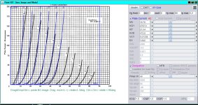
May I ask you what you are going to build with that CK6419 which is extremely low power, both filament and plate.
Less than 200uA of anode current in triode and the pentode curves end with 50uA.
You picked the maybe most unsuitable - or at least most uncomfortable - candidate for a curve fitting exercise.
It took me quite some time and labor to come up with anything usable.
I get a somewhat decent fit between -1V and -5V Vg1 but beyond that ... no way ...
It seems that the mu is quite variable over the range especially towards higher negative Vg.
It is strange anyhow why they show a triode plot up to 90V when they say that max V is 25V in the first place.
Also, the Raytheon DS does not give electrode capacitances; I took arbitrary numbers from a similar DF96 tube.
Anyway ... here's my best effort, mediocre at best though ... give it a try.
Attachments
The 6J5GT is not referenced to 6SN7 because 6J5 is only one triode, while 6SN7 is a twin.Thank you rongon!
I tried to cross reference the 6J5GT to identify a relevant model using this tube substitution source - https://www.worldradiohistory.com/B...ks/SAMS-Tube-Substitution-Handbook-Vol.-7.pdf
It did not provide a reference to a 6SN7.
How did you determine that that model was usable?
Also pinouts do not match. So by definition it is not a substitution or plug in replacement.
But electrically it is common knowledge that one 6J5GT matches 1/2 of 6SN7.
One source (in the middle of this page): http://r-type.org/exhib/aaa0074.htm
Thank you once again Sorento!
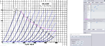
Fair point on the fact that the 6SN7 is a dual and the 6j5GT is a single so they would not be direct replacements.
I was able to download and install the curve mapping tool.
Attached is my fit to the 6j5GT curves which I do not believe is too bad; especially, if I stick to currents below 5mA.
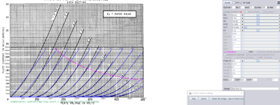
For comparative purposes I pushed the curves for a 6SN7GTB under the same fit and the result is also attached.
The scale difference makes the qualitative comparison of the goodness of the fit a bit tricky, but I would surmise that it is still reasonable and that using a 6SN7GT model to simulate a 6J5GT is viable per the link you pointed to.
Tubes are a relatively new topic to me so I appreciate the enlightenment on DHT as I do not believe that any of the texts that I have been reading touched on this.
Now that I know what I am looking for I did come across a model for a DHT through a link on the curve fitting program page that I am going to look at - http://www.dmitrynizh.com/3a5-phono.htm
I appreciate all of your efforts to fit the CK6419!
I will have a look at it in the coming days and let you know how it works out.
My plan is to use these as a preamplifier front end in a rebuild of an integrated amplifier that I use in my workshop.
It is built into a Dynaco SCA-80Q chassis into which I originally kludged a set of the Oatley Electronics headphone amplifiers that used the CK6418.
I put my own spin on the circuitry (something along the lines of the Curry amp - https://www.tubecad.com/2005/January/blog0027.htm) and the thing is a mechanical mess so it has some problems that neither I nor my friends have ever been to to completely correct.
Now that I have developed a capability to fabricate good PCB's I intend to build a solid design this time.
Furthermore, one of the issues with the 6418's is its propensity for microphonics and i am tired of this taking of on me from time-to-time.
I found a different thread on DiyAudio that discussed the subminiature tubes and it suggested that the 6419 was the best of the lot with regards to microphonics.
I like the subminiatures like the 6418/9 for this type of project since I do not have to generate the really high voltages or the resulting heat.
I agree that the 6419 is not looking like the most robust or appropriate device for the design, but answering that is part of why I am looking for a model.
Any alternate suggestions or recommendations in the subminiature class?
Fair point on the fact that the 6SN7 is a dual and the 6j5GT is a single so they would not be direct replacements.
I was able to download and install the curve mapping tool.
Attached is my fit to the 6j5GT curves which I do not believe is too bad; especially, if I stick to currents below 5mA.
For comparative purposes I pushed the curves for a 6SN7GTB under the same fit and the result is also attached.
The scale difference makes the qualitative comparison of the goodness of the fit a bit tricky, but I would surmise that it is still reasonable and that using a 6SN7GT model to simulate a 6J5GT is viable per the link you pointed to.
Tubes are a relatively new topic to me so I appreciate the enlightenment on DHT as I do not believe that any of the texts that I have been reading touched on this.
Now that I know what I am looking for I did come across a model for a DHT through a link on the curve fitting program page that I am going to look at - http://www.dmitrynizh.com/3a5-phono.htm
I appreciate all of your efforts to fit the CK6419!
I will have a look at it in the coming days and let you know how it works out.
My plan is to use these as a preamplifier front end in a rebuild of an integrated amplifier that I use in my workshop.
It is built into a Dynaco SCA-80Q chassis into which I originally kludged a set of the Oatley Electronics headphone amplifiers that used the CK6418.
I put my own spin on the circuitry (something along the lines of the Curry amp - https://www.tubecad.com/2005/January/blog0027.htm) and the thing is a mechanical mess so it has some problems that neither I nor my friends have ever been to to completely correct.
Now that I have developed a capability to fabricate good PCB's I intend to build a solid design this time.
Furthermore, one of the issues with the 6418's is its propensity for microphonics and i am tired of this taking of on me from time-to-time.
I found a different thread on DiyAudio that discussed the subminiature tubes and it suggested that the 6419 was the best of the lot with regards to microphonics.
I like the subminiatures like the 6418/9 for this type of project since I do not have to generate the really high voltages or the resulting heat.
I agree that the 6419 is not looking like the most robust or appropriate device for the design, but answering that is part of why I am looking for a model.
Any alternate suggestions or recommendations in the subminiature class?
Attachments
@schuelker :
congrats, quick learning, it took me more than an evening to master the paint tools ...
triodes are normally easy, the pentodes are more challenging though.
concerning CK6419: you can import my model into the tool and try to improve on mine.
about Subminis: you may want to have a look on the russian "rod tubes".
e.g.: 1Ж24Б (signal amp) or 1П24Б (power amp). Follow the links further down on this page:
https://www.radiomuseum.org/tubes/tube_1j24b.html
https://www.radiomuseum.org/tubes/tube_1p24b.html
These DHT subminis are of unique construction. The main feature of rod tubes is the absence of grids for the formation of electron
flow and its control: instead of grids, they use rigid metal rods specifically located between the anode and cathode.
https://www.radiomuseum.org/forumdata/upload/radio_1960_no7_34_38_english_10_11_2011.pdf
For a search, the kyrillic 1Ж24Б is often transliterated as 1j24b, 1SH24b, 1ZH24b on the web, and 1П24Б as 1p24b.
Some years ago I built a tiny PP stereo power amp 2 x 4W output using 4 x 1j24b and 4 x 1p24b which fits into a small atx power supply box incl mains transformer, 2 x OPT, iec connector & switch. It takes no more than 17W from mains at idle, real power ... :
I actually built two "power" amps with these:
Zwerg 2 (Dwarf #2):
congrats, quick learning, it took me more than an evening to master the paint tools ...
triodes are normally easy, the pentodes are more challenging though.
concerning CK6419: you can import my model into the tool and try to improve on mine.
about Subminis: you may want to have a look on the russian "rod tubes".
e.g.: 1Ж24Б (signal amp) or 1П24Б (power amp). Follow the links further down on this page:
https://www.radiomuseum.org/tubes/tube_1j24b.html
https://www.radiomuseum.org/tubes/tube_1p24b.html
These DHT subminis are of unique construction. The main feature of rod tubes is the absence of grids for the formation of electron
flow and its control: instead of grids, they use rigid metal rods specifically located between the anode and cathode.
https://www.radiomuseum.org/forumdata/upload/radio_1960_no7_34_38_english_10_11_2011.pdf
For a search, the kyrillic 1Ж24Б is often transliterated as 1j24b, 1SH24b, 1ZH24b on the web, and 1П24Б as 1p24b.
Some years ago I built a tiny PP stereo power amp 2 x 4W output using 4 x 1j24b and 4 x 1p24b which fits into a small atx power supply box incl mains transformer, 2 x OPT, iec connector & switch. It takes no more than 17W from mains at idle, real power ... :
The kind of directly heated tubes nobody is talking about are Russian rod pentodes. These tubes have super efficient filaments that can be practically run on one or two NiCd batteries, making clumsy DC filament supplies unnecessary.
I actually built two "power" amps with these:
Zwerg 2 (Dwarf #2):
- push-pull- all pentode DHT - Gnfb - 100 V line transformer OPT 7.5k / 8 8hm
- 8 rod tubes (2 x 1j24b + 2 x 1p24b per channel)
- 2 x 4 W output into 8 ohm - 30 W input from mains
- fits into a small atx power supply box incl p.s., iec mains connector & switch
- 15 x 14 x 8.5...
Hi gentlemen,
I'm the beginner to starting learning spice model, one point in my mind now is, if I have the real curve data exported from the curve tracer, like uTracer, how can I make the spice model file from those raw data? I'm the software guy, and may use C#, Python or JavaScript to generate a small software tool to make it.
Can anyone help on that?
Thanks.
328A SPICE Models.

Code:
**** 328A ******************************************
* Created on 10/17/2024 19:30 using paint_kip.jar
* www.dmitrynizh.com/tubeparams_image.htm
* Plate Curves image file: 328A.jpg
* Data source link: <plate curves URL>
*----------------------------------------------------------------------------------
.SUBCKT 328A P G2 G K ; LTSpice tetrode.asy pinout
* .SUBCKT 328A P G K G2 ; Koren Pentode Pspice pinout
+ PARAMS: MU=21.7 KG1=2970 KP=133.64 KVB=12 VCT=0.2 EX=1.316 KG2=4200 KNEE=2.76 KVC=2.57
+ KLAM=9.8E-7 KLAMG=5.325E-5 KNEE2=9.2 KNEX=2.7  KNK=-0.044 KNG=0.006
+ CCG=1.3P CGP=6.5P CCP=3.2P RGI=2000.0
* Vp_MAX=200 Ip_MAX=13 Vg_step=1 Vg_start=0 Vg_count=8
* X_MIN=67 Y_MIN=132 X_SIZE=311 Y_SIZE=338 FSZ_X=1183 FSZ_Y=778 XYGrid=false
* Rp=1400 Vg_ac=20 P_max=25 Vg_qui=-3.5 Vp_qui=300
* showLoadLine=n showIp=y isDHP=n isPP=n isAsymPP=n isUL=n showDissipLimit=n
* showIg1=n isInputSnapped=y addLocalNFB=n
* XYProjections=n harmonicPlot=y dissipPlot=n
* UL=0.43 EG2=135 gridLevel2=n addKink=n isTanhKnee=y advSigmoid=n
*----------------------------------------------------------------------------------
RE1  7 0  1G    ; DUMMY SO NODE 7 HAS 2 CONNECTIONS
E1   7 0  VALUE=  ; E1 BREAKS UP LONG EQUATION FOR G1.
+{V(G2,K)/KP*LOG(1+EXP((1/MU+(VCT+V(G,K))/SQRT(KVB+V(G2,K)*V(G2,K)))*KP))}
RE2  6 0  1G    ; DUMMY SO NODE 6 HAS 2 CONNECTIONS
E2  6 0  VALUE={(PWR(V(7),EX)+PWRS(V(7),EX))} ; Kg1 times KIT current
G1   P K  VALUE={V(6)/KG1*ATAN((V(P,K)+KNEX)/KNEE)*TANH(V(P,K)/KNEE2)*(1+KLAMG*V(P,K))+KLAM*V(P,K)}
* Alexander Gurskii screen current, see audioXpress 2/2011
RE4K 4K K 1G ; Dummy, per Alex request
E4K 4K  4 VALUE={0} ; Dummy, per Alex request
G4K 4K K VALUE={V(6)/KG2*(KVC-ATAN((V(P,K)+KNEX)/KNEE)*TANH(V(P,K)/KNEE2))/(1+KLAMG*V(P,K))}
RCP  P K  1G     ; FOR CONVERGENCE
C1   K G  {CCG}  ; CATHODE-GRID 1
C2   G P  {CGP}  ; GRID 1-PLATE
C3   K P  {CCP}  ; CATHODE-PLATE
R1   G 5  {RGI}  ; FOR GRID CURRENT
D3   5 K  DX     ; FOR GRID CURRENT }
.MODEL DX D(IS=1N RS=1 CJO=10PF TT=1N)
.ENDS
*$


* The following triode model is derived from pentode model, see above.
* In the triode model, all spice parameters come directly from the pentode model, except for Kg1,
* which for triode-strapped pentodes is derived from pentode's Kg1, Kg2 and Kvc as
*
*    4Kg1Kg2 / ((2Kvc-Pi)(2Kg1+PiKg2))

**** 328A ******************************************
* Created on 10/17/2024 19:30 using paint_kit.jar 4.7
* www.dmitrynizh.com/tubeparams_image.htm
* Plate Curves image file: 328A.jpg
* Data source link: <plate curves URL>
*----------------------------------------------------------------------------------
.SUBCKT TRIODE_328A 1 2 3 ; Plate Grid Cathode
+ PARAMS: CCG=1.3P  CGP=6.5P CCP=3.2P RGI=2000
+ MU=21.7 KG1=1304.85 KP=133.64 KVB=12 VCT=0.2 EX=1.316
* Vp_MAX=200 Ip_MAX=13 Vg_step=1 Vg_start=0 Vg_count=8
* Rp=1400 Vg_ac=20 P_max=25 Vg_qui=-3.5 Vp_qui=300
* X_MIN=67 Y_MIN=132 X_SIZE=311 Y_SIZE=338 FSZ_X=1183 FSZ_Y=778 XYGrid=false
* showLoadLine=n showIp=y isDHT=n isPP=n isAsymPP=n showDissipLimit=n
* showIg1=n gridLevel2=n isInputSnapped=y
* XYProjections=n harmonicPlot=y dissipPlot=n
*----------------------------------------------------------------------------------
E1 7 0 VALUE={V(1,3)/KP*LOG(1+EXP(KP*(1/MU+(VCT+V(2,3))/SQRT(KVB+V(1,3)*V(1,3)))))}
RE1 7 0 1G  ; TO AVOID FLOATING NODES
G1 1 3 VALUE={(PWR(V(7),EX)+PWRS(V(7),EX))/KG1}
RCP 1 3 1G   ; TO AVOID FLOATING NODES
C1 2 3 {CCG} ; CATHODE-GRID
C2 2 1 {CGP} ; GRID=PLATE
C3 1 3 {CCP} ; CATHODE-PLATE
D3 5 3 DX ; POSITIVE GRID CURRENT
R1 2 5 {RGI} ; POSITIVE GRID CURRENT
.MODEL DX D(IS=1N RS=1 CJO=10PF TT=1N)
.ENDS
*$Hello HiTubeHi gentlemen,
I'm the beginner to starting learning spice model, one point in my mind now is, if I have the real curve data exported from the curve tracer, like uTracer, how can I make the spice model file from those raw data? I'm the software guy, and may use C#, Python or JavaScript to generate a small software tool to make it.
Can anyone help on that?
Thanks.
The easiest way is to plot your RAW data, and provide the graph(s) in this thread, kindly asking for a spice model generated from it.
Next easier way is to install Dmitri's paint kit tool, load your graphs and dive into the fascinating world of manually tuning spice models. One loves or hates it, like driving car with manual gearbox!
I personally prefer the most complicated way (tuning the spice parameter directly in LTspice, compare results with overlaid semitransparent RAWdata graph).
Simply because there is currently no better way to create an i6 model😏 - but wait!🤔
What if there would be any software guy on earth, willing to create a kind of paint kit tool for i6 models?
Wow - that would be like heaven!! 😍😊😛😀
But stop dreaming, Adrian, be realistic... Who wants to waist time just for convenient i6 creation... 🙄
BR Adrian
Thanks Adrian.
Sounds like there is no one made the similar tool yet, and looks an impossible mission so far 😒 Sorry I don't know what i6 model is, could you explain a little bit, appreciated🙂
The reason I wanna do that is... I build a tube curve tracer, and want to export the spice model directly from the control software. As to the way you mentioned to fit the data from the curve image, looks not very accurate, and some curves may not be fitted for some tubes...
So, if I understand the internal mechanism/theory of how to generate the spice model from the curve RAW data, I would be happy to start from there...
Thanks
Hello HiTube
Please note that "THE spice model theory" does not exist. There are plenty, all with its pro's and con's. It's about a dozen different approaches, and those from me are indicated with .i + Number of version, which is currently 6. If you wish an (incomplete) overview, this paper might help you:
https://drive.google.com/file/d/1CF61JpKPAK8pFmsGam4kmcbCehU1qxJz/view
BTW, what kind of Tube Tracer did you build? Is it a uTracer from Ronald (dos4ever.com)?
I developed my own Tracer, because I wished to measure also the small initial velocity grid current, dominating the total grid current between -1V < Vg < 0V.
You can find some decription of it here:
https://adrianimmler.simplesite.com/452104653/448264046
BTW, if you are interested in a triode model with good accuracy for negative Grid voltage only, then the Norman Koren model might be a suitable for you.
It provides good results, regardless if the parameter tuning is done manually or automated. Easiest way for automated fit is by excel, using its solver to tune for minimal sum of squared deviations.
Or use a Phython script (which was a recent "rainy day project" of mine)
BR Adrian
Thanks Adrian for the clarification.
Unfortunately the link to the google website is not working for me.... I cannot access google website, but do appreciate your help. I may try to find something on some other websites...
The curve tracer I made is not uTracer, it is designed by myself. It should be not suitable to post some pictures here... and I don't have my personal Blog to share it 🙁
Your iTracer looks pretty nice! You are using two transformers to achieve the high plate voltage, correct?
Yes, I'm looking into Norman Koren model to clarify how it is working, may have a try in my control software, it is implemented by using JavaScript 🙂
Thanks
Hi HiTube
You can find the mentioned paper also here:
https://de.scribd.com/document/391613868/Best-of-History-s-Merged-to-New-Vacuum-Tube-Spice-Models
And yes, I use the two transformers to achieve the high voltages needed for Anode and also Grid2 (if present in the measured tube). Using transformers for this purpose has also the advantage of selectable series- or parallel-connection of the both secondary windings. This way, I can either get 400Vmax pulses up to 180mA or 200Vmax pulses up to 360mA, to cover a wide range of tubes.
BR Adrian
Adrian: At the risk of being slightly OT, why did you choose a discrete logarithmic amplifier instead of an "off-the-shelf" chip from Analog Devices or Texas Instruments? (I first got into log amps in darkroom photography at the time that 8 bit DAC's were common.)
Hi zintolo
Freshly backed:
Hi Adrian, can I please ask you to double check this model of the 6P13P? I tried few times over the years, but it always went with the screen getting alot of current, and the anode not at all. Thanks in advance, Roberto.
Hi Roberto
I just gave a spin to my 6P13P i4 model, and it worked fine.
But for sure, a model running stable in one sim might still causing issues in another sim.
Hence, can you please send me your .asc file?
Thanks
BR Adrian
I just gave a spin to my 6P13P i4 model, and it worked fine.
But for sure, a model running stable in one sim might still causing issues in another sim.
Hence, can you please send me your .asc file?
Thanks
BR Adrian
- Home
- Amplifiers
- Tubes / Valves
- Vacuum Tube SPICE Models