EL38 SPICE Models.
Code:
**** EL38 ******************************************
* Created on 12/17/2024 20:49 using paint_kip.jar
* www.dmitrynizh.com/tubeparams_image.htm
* Plate Curves image file: EL38.jpg
* Data source link: <plate curves URL>
*----------------------------------------------------------------------------------
.SUBCKT EL38 P G2 G K ; LTSpice tetrode.asy pinout
* .SUBCKT EL38 P G K G2 ; Koren Pentode Pspice pinout
+ PARAMS: MU=17.3 KG1=522.5 KP=80.71 KVB=61.44 VCT=0.008 EX=1.386 KG2=1081.5 KNEE=18.91 KVC=2.57
+ KLAM=7.992E-6 KLAMG=2.346E-4 KNEE2=29.86 KNEX=0.1762  KNK=-0.7257 KNG=0.006118 KNPL=0.1914 KNSL=10.89 KNPR=470.4 KNSR=7.395
+ CCG=17.5P CGP=1.2P CCP=6.5P RGI=2000.0
* Vp_MAX=400 Ip_MAX=300 Vg_step=2 Vg_start=0 Vg_count=10
* X_MIN=47 Y_MIN=108 X_SIZE=495 Y_SIZE=370 FSZ_X=1381 FSZ_Y=797 XYGrid=false
* Rp=904.6 Vg_ac=8.349 P_max=25 Vg_qui=-9 Vp_qui=202.02
* showLoadLine=y showIp=y isDHP=n isPP=n isAsymPP=n isUL=n showDissipLimit=y
* showIg1=n isInputSnapped=y addLocalNFB=n
* XYProjections=n harmonicPlot=y dissipPlot=y
* UL=0.43 EG2=275 gridLevel2=n addKink=y isTanhKnee=y advSigmoid=n
*----------------------------------------------------------------------------------
RE1  7 0  1G    ; DUMMY SO NODE 7 HAS 2 CONNECTIONS
E1   7 0  VALUE=  ; E1 BREAKS UP LONG EQUATION FOR G1.
+{V(G2,K)/KP*LOG(1+EXP((1/MU+(VCT+V(G,K))/SQRT(KVB+V(G2,K)*V(G2,K)))*KP))}
RE2  6 0  1G    ; DUMMY SO NODE 6 HAS 2 CONNECTIONS
E2  6 0  VALUE={(PWR(V(7),EX)+PWRS(V(7),EX))} ; Kg1 times KIT current
RE21 21 0 1
E21  21 0 VALUE={V(6)/KG1*ATAN((V(P,K)+KNEX)/KNEE)*TANH(V(P,K)/KNEE2)} ; Ip with knee but no slope and no kink
RE22 22 0 1 ; E22: kink curr deviation for plate
E22  22 0 VALUE={V(21)*LIMIT(KNK-V(G,K)*KNG,0,0.3)*(-ATAN((V(P,K)-KNPL)/KNSL)+ATAN((V(P,K)-KNPR)/KNSR))}
G1   P  K  VALUE={V(21)*(1+KLAMG*V(P,K))+KLAM*V(P,K) + V(22)}
* Alexander Gurskii screen current, see audioXpress 2/2011, with slope and kink added
RE43 43 K 1G ; Dummy
E43  43 G2 VALUE={0} ; Dummy
G2   43 K  VALUE={V(6)/KG2*(KVC-ATAN((V(P,K)+KNEX)/KNEE)*TANH(V(P,K)/KNEE2))/(1+KLAMG*V(P,K))-V(22)}
RCP  P K  1G     ; FOR CONVERGENCE
C1   K G  {CCG}  ; CATHODE-GRID 1
C2   G P  {CGP}  ; GRID 1-PLATE
C3   K P  {CCP}  ; CATHODE-PLATE
R1   G 5  {RGI}  ; FOR GRID CURRENT
D3   5 K  DX     ; FOR GRID CURRENT }
.MODEL DX D(IS=1N RS=1 CJO=10PF TT=1N)
.ENDS
Attachments
Last edited:
Hi everyone,
I’m looking for a complete LTspice model of the simple tetrode (not beam!) RCA A 24, including the range between 0 and 80 volts where the values are unstable. It’s important for my research to have this range included, as I need to visualize and analyze the behavior in this region.
I’ve found a model, but unfortunately, it doesn’t include this data and doesn’t allow proper simulation of that range. Does anyone have a more complete model available or suggestions on how to modify it to incorporate the missing portion?
Let me know if it's possible.
Thanks in advance for your help!
Attachments
Hi Daniela1234
The last time I modeled a tube with secondary emission effect, I failed due to convergence issues. But I will try again, perhaps I willcope to get a stable model. But it will take several days, just FYI.
BR Adrian
The last time I modeled a tube with secondary emission effect, I failed due to convergence issues. But I will try again, perhaps I willcope to get a stable model. But it will take several days, just FYI.
BR Adrian

Thank you so much for the immediate response! This model is essential for my thesis work, and it would be incredibly helpful if we could make it happen.
In the meantime, I’m working on it myself, and if I manage to get any results, I’ll make sure to upload them here to share with the community. Thanks again for your support!
In the meantime, I’m working on it myself, and if I manage to get any results, I’ll make sure to upload them here to share with the community. Thanks again for your support!
Thank you for your interest! The thesis I’m working on focuses on studying a neuron model using analog signals recorded via a tetrode. Specifically, I’m leveraging the sigmoid behavior it produces in its nonlinear region. Instead of relying on modern transistors, I wanted to explore whether an acceptable model could be achieved using vintage electronics—almost forgotten components like these tubes. My goal is not only to develop the model but also to bring some renewed attention to these amazing, nearly forgotten valves.
Sounds interesting! BTW, my model to mimic the secondary emission effect is Based on a fundamental work of Derk Reefman, who used basically a tanh function for it, the „brother“ of the sig function 😉.
I had found the file, but I don’t understand how to implement it in LTspice, especially because "beam" configurations are always used, which don’t have the typical behavior of standard tetrodes. Can it also be used in the case of the tetrode I mentioned earlier?
Attachments
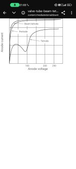
Pentodes as well as Beam Tetrodes supress the secondary effect to a certain amount. The seconary effect is still present in those tubes, but the remaining ampitude might be so strong reduced, that it is no longer visible.
How ever, Derk Reefmans approach is fine for all, pure tetrodes, beam tetrodes or pentodes.
Note that his approach has some weak points:
1) strong influence of each tuning parameter to the others. They don‘t act independently.
2) the secondary effect depends on the Value of Vg2, which is not considered in his approach.
I tried to adress both for my own approach.
Ah, fantastic! That could be a great starting point to work on... Did you try something like this in a model you worked on in the past, or is it the project you’re currently developing?
I’m trying a different approach: using MATLAB to plot the curve dependent on the Vg voltage and then recreating a function from the plotted values. This way, I can simplify the implementation by treating the tetrode as a voltage-controlled generator to simulate that specific nonlinear region.
Maybe you, with more experience, could provide a more expert opinion. I’m a complete beginner, and unfortunately, these topics aren’t covered at university.
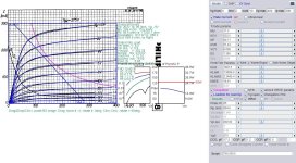
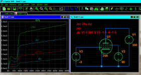
I don't want to interfere ... I was just curious whether Dimitri's paint tool could produce something which would at least look similar to the kinky curves in the data sheet of the 24A. And to my surprise, it can.
I did not invest much time in tuning the model. It is coarse and far from precision.
And I don't pretend that it is the final solution to the problem.
But I wanted to post it nevertheless.
Maybe @Daniela1234 can use it as a test vehicle to resolve problems with the intended LTSpice simulation until Adrian's model is ready, which we know from previous experience will certainly be much more suitable.
Anyway, here it is: The Spice Model is in the text file 24a.txt.
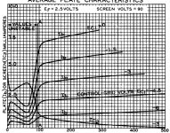
One last remark:
The model tool I used seems to have problems to model the kinks at VG1=0V, they always come out straight.
So you should keep grid voltages always negative, preferably below -1.5V.
And screen current is probably way off and not kinky at all. Which may be O.K. if you use a constant Vg2 in your sim.
Good Luck ...
I did not invest much time in tuning the model. It is coarse and far from precision.
And I don't pretend that it is the final solution to the problem.
But I wanted to post it nevertheless.
Maybe @Daniela1234 can use it as a test vehicle to resolve problems with the intended LTSpice simulation until Adrian's model is ready, which we know from previous experience will certainly be much more suitable.
Anyway, here it is: The Spice Model is in the text file 24a.txt.
One last remark:
The model tool I used seems to have problems to model the kinks at VG1=0V, they always come out straight.
So you should keep grid voltages always negative, preferably below -1.5V.
And screen current is probably way off and not kinky at all. Which may be O.K. if you use a constant Vg2 in your sim.
Good Luck ...
Attachments
Thank you for your valuable work! This afternoon, I’ll try to figure out how to make the most of it and will let you know 🙂
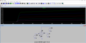
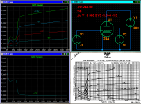
Hi Daniela1234, hi Sorento
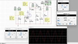
I did in the meantime some trials with my SE Approach, but failed. The issue is, that my method to avoid Ip valleys going into negative range, is a kind of soft clipping. While this is in general an advantage for convergence performance, it is a problem for stronger secondary emission effects like it is the case for this tube. See attached the maximum SE effect I can achieve - far away from the strength it should be.
To solve that, I will need several weeks due to my limited sparetime.
So, I propose to continue with Sorento's model, perhaps with some more fine-tuning.
BR Adrian
Attachments
O.K. then ...
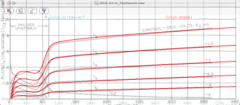
Here's an improved version of the 24-A spice model.
Better fit for the plate currents now and the screen current for -3V does have the appropriate kink, too.
It still does not produce any kinks for Vg1=0V, the responsible equations seem to resolve to zero when fed with 0.
But they appear to work fine now below -0.5V.
I also removed most of the comment lines from the model file, which are not required to run a simulation.
Give it a try ...
Attachments
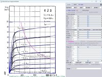
6J3 SPICE Models.
Code:
.SUBCKT 6J3 P G2 G K ; LTSpice tetrode.asy pinout
+ PARAMS: MU=51.2 KG1=968 KP=193.71 KVB=11.16 VCT=0.348 EX=1.4 KG2=4242 KNEE=12 KVC=2.57
+ KLAM=6.6E-7 KLAMG=2.31E-4 KNEE2=16.89 KNEX=62.4  KNK=-0.044 KNG=0.006
+ CCG=8.5P CGP=0.003P CCP=7P RGI=2000.0
RE1  7 0  1G    ; DUMMY SO NODE 7 HAS 2 CONNECTIONS
E1   7 0  VALUE=  ; E1 BREAKS UP LONG EQUATION FOR G1.
+{V(G2,K)/KP*LN(1+EXP((1/MU+(VCT+V(G,K))/SQRT(KVB+V(G2,K)*V(G2,K)))*KP))}
RE2  6 0  1G    ; DUMMY SO NODE 6 HAS 2 CONNECTIONS
E2  6 0  VALUE={(PWR(V(7),EX)+PWRS(V(7),EX))} ; Kg1 times KIT current
G1   P K  VALUE={V(6)/KG1*ATAN((V(P,K)+KNEX)/KNEE)*TANH(V(P,K)/KNEE2)*(1+KLAMG*V(P,K))+KLAM*V(P,K)}
RE4K 4K K 1G ; Dummy, per Alex request
E4K 4K  4 VALUE={0} ; Dummy, per Alex request
G4K 4K K VALUE={V(6)/KG2*(KVC-ATAN((V(P,K)+KNEX)/KNEE)*TANH(V(P,K)/KNEE2))/(1+KLAMG*V(P,K))}
RCP  P K  1G     ; FOR CONVERGENCE
C1   K G  {CCG}  ; CATHODE-GRID 1
C2   G P  {CGP}  ; GRID 1-PLATE
C3   K P  {CCP}  ; CATHODE-PLATE
R1   G 5  {RGI}  ; FOR GRID CURRENT
D3   5 K  DX     ; FOR GRID CURRENT }
.MODEL DX D(IS=1N RS=1 CJO=10PF TT=1N)
.ENDS
Attachments
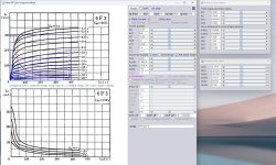
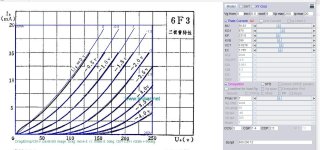
The china 6F3 SPICE Models.
Code:
**** 6F3_P ******************************************
* Created on 02/03/2025 18:22 using paint_kip.jar
* www.dmitrynizh.com/tubeparams_image.htm
* Plate Curves image file: 6F3.jpg
* Data source link: <plate curves URL>
*----------------------------------------------------------------------------------
.SUBCKT 6F3_P P G2 G K ; LTSpice tetrode.asy pinout
* .SUBCKT 6F3 P G K G2 ; Koren Pentode Pspice pinout
+ PARAMS: MU=10.67 KG1=506 KP=33.25 KVB=12 VCT=0.038 EX=1.4 KG2=4200 KNEE=7.56 KVC=2.57
+ KLAM=1.98E-6 KLAMG=2.97E-4  KD=0.8357 KC=0.1036 KR1=0.001417 KR2=0.0992 KVBG=0.02448 KB1=1.919 KB2=1.533 KB3=2.079 KB4=0.5145 KVBGI=0.000931 KNK=-0.1577 KNG=0.01393 KNPL=0.01098 KNSL=212.39 KNPR=111.15 KNSR=27.38
+ CCG=3P CGP=1.4P CCP=2.5P RGI=2000.0
* Vp_MAX=400 Ip_MAX=300 Vg_step=2 Vg_start=-10 Vg_count=10
* X_MIN=53 Y_MIN=173 X_SIZE=355 Y_SIZE=265 FSZ_X=1153 FSZ_Y=1040 XYGrid=false
* Rp=1400 Vg_ac=20 P_max=7 Vg_qui=-19 Vp_qui=300
* showLoadLine=n showIp=y isDHP=n isPP=n isAsymPP=n isUL=n showDissipLimit=y
* showIg1=n isInputSnapped=y addLocalNFB=n
* XYProjections=n harmonicPlot=y dissipPlot=n
* UL=0.43 EG2=210 gridLevel2=n addKink=y isTanhKnee=n advSigmoid=y
*----------------------------------------------------------------------------------
RE1  7 0  1G    ; DUMMY SO NODE 7 HAS 2 CONNECTIONS
E1   7 0  VALUE=  ; E1 BREAKS UP LONG EQUATION FOR G1.
+{V(G2,K)/KP*LOG(1+EXP((1/MU+(VCT+V(G,K))/SQRT(KVB+V(G2,K)*V(G2,K)))*KP))}
RE2  6 0  1G    ; DUMMY SO NODE 6 HAS 2 CONNECTIONS
E2  6 0  VALUE={(PWR(V(7),EX)+PWRS(V(7),EX))} ; Kg1 times KIT current
E4   8 0  VALUE={V(P,K)/KNEE/(KVBGI+V(6)*KVBG)}
E5  81 0  VALUE={PWR(V(8),KB1)}
E6  82 0  VALUE={PWR(V(8),KB2)}
E7  83 0  VALUE={PWR(V(8),KB3)}
E8   9 0  VALUE={PWR(1-EXP(-V(81)*(KC+KR1*V(82))/(KD+KR2*V(83))),KB4)*1.5708}
RE4  8 0  1
RE5 81 0  1
RE6 82 0  1
RE7 83 0  1
RE8  9 0  1
RE21 21 0 1
E21  21 0 VALUE={V(6)/KG1*V(9)} ; Ip with knee but no slope and no kink
RE22 22 0 1 ; E22: kink curr deviation for plate
E22  22 0 VALUE={V(21)*LIMIT(KNK-V(G,K)*KNG,0,0.3)*(-ATAN((V(P,K)-KNPL)/KNSL)+ATAN((V(P,K)-KNPR)/KNSR))}
G1   P K  VALUE={V(21)*(1+KLAMG*V(P,K))+KLAM*V(P,K) + V(22)}
G2   G2 K  VALUE={V(6)/KG2*(KVC-V(9))/(1+KLAMG*V(P,K)) - V(22)}
RCP  P K  1G     ; FOR CONVERGENCE
C1   K G  {CCG}  ; CATHODE-GRID 1
C2   G P  {CGP}  ; GRID 1-PLATE
C3   K P  {CCP}  ; CATHODE-PLATE
R1   G 5  {RGI}  ; FOR GRID CURRENT
D3   5 K  DX     ; FOR GRID CURRENT }
.MODEL DX D(IS=1N RS=1 CJO=10PF TT=1N)
.ENDS
*$


**** 6F3_T ******************************************
* Created on 02/03/2025 19:09 using paint_kit.jar 3.1
* www.dmitrynizh.com/tubeparams_image.htm
* Plate Curves image file: 6F3_T.jpg
* Data source link:
*----------------------------------------------------------------------------------
.SUBCKT TRIODE_6F3_T 1 2 3 ; Plate Grid Cathode
+ PARAMS: CCG=3P  CGP=1.4P CCP=2.5P RGI=2000
+ MU=56.63 KG1=870 KP=231.8 KVB=396 VCT=0.6278 EX=1.705
* Vp_MAX=250 Ip_MAX=20 Vg_step=0.5 Vg_start=0 Vg_count=9
* Rp=4000 Vg_ac=55 P_max=7 Vg_qui=-48 Vp_qui=300
* X_MIN=72 Y_MIN=99 X_SIZE=589 Y_SIZE=470 FSZ_X=1382 FSZ_Y=1047 XYGrid=false
* showLoadLine=n showIp=y isDHT=n isPP=n isAsymPP=n showDissipLimit=y
* showIg1=n gridLevel2=n isInputSnapped=n
* XYProjections=n harmonicPlot=n dissipPlot=n
*----------------------------------------------------------------------------------
E1 7 0 VALUE={V(1,3)/KP*LOG(1+EXP(KP*(1/MU+(VCT+V(2,3))/SQRT(KVB+V(1,3)*V(1,3)))))}
RE1 7 0 1G  ; TO AVOID FLOATING NODES
G1 1 3 VALUE={(PWR(V(7),EX)+PWRS(V(7),EX))/KG1}
RCP 1 3 1G   ; TO AVOID FLOATING NODES
C1 2 3 {CCG} ; CATHODE-GRID
C2 2 1 {CGP} ; GRID=PLATE
C3 1 3 {CCP} ; CATHODE-PLATE
D3 5 3 DX ; POSITIVE GRID CURRENT
R1 2 5 {RGI} ; POSITIVE GRID CURRENT
.MODEL DX D(IS=1N RS=1 CJO=10PF TT=1N)
.ENDS
*$
Attachments
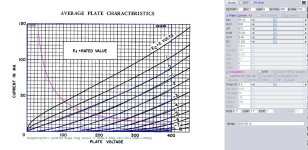
8334 SPICE Models.
Code:
**** 8334 ******************************************
* Created on 02/04/2025 18:19 using paint_kit.jar 3.1
* www.dmitrynizh.com/tubeparams_image.htm
* Plate Curves image file: 8334.jpg
* Data source link:
*----------------------------------------------------------------------------------
.SUBCKT 8334 1 2 3 ; Plate Grid Cathode
+ PARAMS: CCG=5.5P  CGP=1.7P CCP=1P RGI=2000
+ MU=59.14 KG1=300 KP=472 KVB=53.25 VCT=0.48 EX=1.302
* Vp_MAX=400 Ip_MAX=150 Vg_step=1 Vg_start=0 Vg_count=9
* Rp=4000 Vg_ac=55 P_max=4.4 Vg_qui=-48 Vp_qui=300
* X_MIN=178 Y_MIN=123 X_SIZE=699 Y_SIZE=519 FSZ_X=1549 FSZ_Y=779 XYGrid=false
* showLoadLine=n showIp=y isDHT=n isPP=n isAsymPP=n showDissipLimit=y
* showIg1=n gridLevel2=n isInputSnapped=n
* XYProjections=n harmonicPlot=n dissipPlot=n
*----------------------------------------------------------------------------------
E1 7 0 VALUE={V(1,3)/KP*LOG(1+EXP(KP*(1/MU+(VCT+V(2,3))/SQRT(KVB+V(1,3)*V(1,3)))))}
RE1 7 0 1G  ; TO AVOID FLOATING NODES
G1 1 3 VALUE={(PWR(V(7),EX)+PWRS(V(7),EX))/KG1}
RCP 1 3 1G   ; TO AVOID FLOATING NODES
C1 2 3 {CCG} ; CATHODE-GRID
C2 2 1 {CGP} ; GRID=PLATE
C3 1 3 {CCP} ; CATHODE-PLATE
D3 5 3 DX ; POSITIVE GRID CURRENT
R1 2 5 {RGI} ; POSITIVE GRID CURRENT
.MODEL DX D(IS=1N RS=1 CJO=10PF TT=1N)
.ENDS
*$
Attachments
Last edited:
- Home
- Amplifiers
- Tubes / Valves
- Vacuum Tube SPICE Models