I haven’t found ELL80 models. Can someone post them please?
https://www.robkalmeijer.nl/techniek/electronica/datasheets/e/ell80.pdf
https://www.robkalmeijer.nl/techniek/electronica/datasheets/e/ell80.pdf
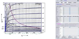
ELL80 SPICE Models.
Code:
**** ELL80 ******************************************
* Created on 02/08/2025 11:22 using paint_kip.jar
* www.dmitrynizh.com/tubeparams_image.htm
* Plate Curves image file: ELL80.jpg
* Data source link: <plate curves URL>
*----------------------------------------------------------------------------------
.SUBCKT ELL80 P G2 G K ; LTSpice tetrode.asy pinout
* .SUBCKT ELL80 P G K G2 ; Koren Pentode Pspice pinout
+ PARAMS: MU=19 KG1=1188 KP=102.11 KVB=12.24 VCT=0.278 EX=1.4 KG2=4200 KNEE=11.76 KVC=2.57
+ KLAM=8.6E-7 KLAMG=9.9E-5   KNK=-0.0983 KNG=0.00606 KNPL=85.5 KNSL=11.22 KNPR=85.5 KNSR=28.42
+ CCG=7P CGP=4.5P CCP=4.2P RGI=2000.0
* Vp_MAX=500 Ip_MAX=100 Vg_step=2 Vg_start=0 Vg_count=8
* X_MIN=103 Y_MIN=57 X_SIZE=620 Y_SIZE=494 FSZ_X=1381 FSZ_Y=720 XYGrid=false
* Rp=1400 Vg_ac=20 P_max=6 Vg_qui=-7 Vp_qui=300
* showLoadLine=n showIp=y isDHP=n isPP=n isAsymPP=n isUL=n showDissipLimit=y
* showIg1=n isInputSnapped=y addLocalNFB=n
* XYProjections=n harmonicPlot=y dissipPlot=n
* UL=0.43 EG2=250 gridLevel2=n addKink=y isTanhKnee=n advSigmoid=n
*----------------------------------------------------------------------------------
RE1  7 0  1G    ; DUMMY SO NODE 7 HAS 2 CONNECTIONS
E1   7 0  VALUE=  ; E1 BREAKS UP LONG EQUATION FOR G1.
+{V(G2,K)/KP*LOG(1+EXP((1/MU+(VCT+V(G,K))/SQRT(KVB+V(G2,K)*V(G2,K)))*KP))}
RE2  6 0  1G    ; DUMMY SO NODE 6 HAS 2 CONNECTIONS
E2  6 0  VALUE={(PWR(V(7),EX)+PWRS(V(7),EX))} ; Kg1 times KIT current
RE21 21 0 1
E21  21 0 VALUE={V(6)/KG1*ATAN(V(P,K)/KNEE)} ; Ip with knee but no slope and no kink
RE22 22 0 1 ; E22: kink curr deviation for plate
E22  22 0 VALUE={V(21)*LIMIT(KNK-V(G,K)*KNG,0,0.3)*(-ATAN((V(P,K)-KNPL)/KNSL)+ATAN((V(P,K)-KNPR)/KNSR))}
G1   P  K  VALUE={V(21)*(1+KLAMG*V(P,K))+KLAM*V(P,K) + V(22)}
* Alexander Gurskii screen current, see audioXpress 2/2011, with slope and kink added
RE43 43 K 1G ; Dummy
E43  43 G2 VALUE={0} ; Dummy
G2   43 K  VALUE={V(6)/KG2*(KVC-ATAN(V(P,K)/KNEE))/(1+KLAMG*V(P,K))-V(22)}
RCP  P K  1G     ; FOR CONVERGENCE
C1   K G  {CCG}  ; CATHODE-GRID 1
C2   G P  {CGP}  ; GRID 1-PLATE
C3   K P  {CCP}  ; CATHODE-PLATE
R1   G 5  {RGI}  ; FOR GRID CURRENT
D3   5 K  DX     ; FOR GRID CURRENT }
.MODEL DX D(IS=1N RS=1 CJO=10PF TT=1N)
.ENDS
Attachments

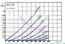
The china 6c12 SPICE models.
Code:
**** 6C12 ******************************************
* Created on 02/13/2025 11:31 using paint_kit.jar 3.1
* www.dmitrynizh.com/tubeparams_image.htm
* Plate Curves image file: *.jpg
* Data source link:
*----------------------------------------------------------------------------------
.SUBCKT 6C12 1 2 3 ; Plate Grid Cathode
+ PARAMS: CCG=3.7P  CGP=0.08P CCP=1.5P RGI=2000
+ MU=74.59 KG1=172.5 KP=308 KVB=89.62 VCT=0.198 EX=1.484
* Vp_MAX=200 Ip_MAX=30 Vg_step=0.5 Vg_start=0 Vg_count=7
* Rp=4000 Vg_ac=55 P_max=2 Vg_qui=-48 Vp_qui=300
* X_MIN=65 Y_MIN=171 X_SIZE=425 Y_SIZE=244 FSZ_X=1260 FSZ_Y=630 XYGrid=true
* showLoadLine=n showIp=y isDHT=n isPP=n isAsymPP=n showDissipLimit=y
* showIg1=n gridLevel2=n isInputSnapped=n
* XYProjections=n harmonicPlot=n dissipPlot=n
*----------------------------------------------------------------------------------
E1 7 0 VALUE={V(1,3)/KP*LOG(1+EXP(KP*(1/MU+(VCT+V(2,3))/SQRT(KVB+V(1,3)*V(1,3)))))}
RE1 7 0 1G  ; TO AVOID FLOATING NODES
G1 1 3 VALUE={(PWR(V(7),EX)+PWRS(V(7),EX))/KG1}
RCP 1 3 1G   ; TO AVOID FLOATING NODES
C1 2 3 {CCG} ; CATHODE-GRID
C2 2 1 {CGP} ; GRID=PLATE
C3 1 3 {CCP} ; CATHODE-PLATE
D3 5 3 DX ; POSITIVE GRID CURRENT
R1 2 5 {RGI} ; POSITIVE GRID CURRENT
.MODEL DX D(IS=1N RS=1 CJO=10PF TT=1N)
.ENDS
Attachments
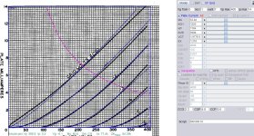
6EM7 SPICE models.
Code:
**** 6EM7_1 ******************************************
* Created on 02/17/2025 10:23 using paint_kit.jar 3.1
* www.dmitrynizh.com/tubeparams_image.htm
* Plate Curves image file: 6EM7.jpg
* Data source link:
*----------------------------------------------------------------------------------
.SUBCKT 6EM7_1 1 2 3 ; Plate Grid Cathode
+ PARAMS: CCG=2.2P CGP=4.8P CCP=0.6P RGI=2000
+ MU=63.84 KG1=1200 KP=1184 KVB=5688 VCT=3.955E-5 EX=1.218
* Vp_MAX=400 Ip_MAX=14 Vg_step=1 Vg_start=0 Vg_count=7
* Rp=4000 Vg_ac=55 P_max=1.5 Vg_qui=-48 Vp_qui=300
* X_MIN=51 Y_MIN=38 X_SIZE=699 Y_SIZE=595 FSZ_X=1292 FSZ_Y=754 XYGrid=false
* showLoadLine=n showIp=y isDHT=n isPP=n isAsymPP=n showDissipLimit=y
* showIg1=n gridLevel2=n isInputSnapped=n
* XYProjections=n harmonicPlot=n dissipPlot=n
*----------------------------------------------------------------------------------
E1 7 0 VALUE={V(1,3)/KP*LOG(1+EXP(KP*(1/MU+(VCT+V(2,3))/SQRT(KVB+V(1,3)*V(1,3)))))}
RE1 7 0 1G ; TO AVOID FLOATING NODES
G1 1 3 VALUE={(PWR(V(7),EX)+PWRS(V(7),EX))/KG1}
RCP 1 3 1G ; TO AVOID FLOATING NODES
C1 2 3 {CCG} ; CATHODE-GRID
C2 2 1 {CGP} ; GRID=PLATE
C3 1 3 {CCP} ; CATHODE-PLATE
D3 5 3 DX ; POSITIVE GRID CURRENT
R1 2 5 {RGI} ; POSITIVE GRID CURRENT
.MODEL DX D(IS=1N RS=1 CJO=10PF TT=1N)
.ENDS
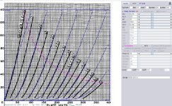
**** 6EM7_2 ** Advanced Grid Current **********************************
* Created on 02/17/2025 11:02 using paint_kit.jar 3.1
* www.dmitrynizh.com/tubeparams_image.htm
* Plate Curves image file: 6EM7_2.jpg
* Data source link:
*----------------------------------------------------------------------------------
.SUBCKT TRIODE_6EM7_2 1 2 3 ; Plate Grid Cathode
+ PARAMS: CCG=7P CGP=10P CCP=1.8P
+ MU=6.216 KG1=255 KP=32 KVB=1056 VCT=0.736 EX=1.008
+ VGOFF=-7.44 IGA=5E-4 IGB=0.306 IGC=1.94 IGEX=1.96
* Vp_MAX=400 Ip_MAX=140 Vg_step=10 Vg_start=0 Vg_count=8
* Rp=4000 Vg_ac=55 P_max=10 Vg_qui=-48 Vp_qui=300
* X_MIN=41 Y_MIN=68 X_SIZE=825 Y_SIZE=720 FSZ_X=1376 FSZ_Y=877 XYGrid=false
* showLoadLine=n showIp=y isDHT=n isPP=n isAsymPP=n showDissipLimit=y
* showIg1=n gridLevel2=y isInputSnapped=n
* XYProjections=n harmonicPlot=n dissipPlot=n
*----------------------------------------------------------------------------------
E1 7 0 VALUE={V(1,3)/KP*LOG(1+EXP(KP*(1/MU+(VCT+V(2,3))/SQRT(KVB+V(1,3)*V(1,3)))))}
RE1 7 0 1G ; TO AVOID FLOATING NODES
G1 1 3 VALUE={(PWR(V(7),EX)+PWRS(V(7),EX))/KG1}
RCP 1 3 1G ; TO AVOID FLOATING NODES
C1 2 3 {CCG} ; CATHODE-GRID
C2 2 1 {CGP} ; GRID=PLATE
C3 1 3 {CCP} ; CATHODE-PLATE
RE2 2 0 1G
EGC 8 0 VALUE={V(2,3)-VGOFF} ; POSITIVE GRID THRESHOLD
GG 2 3 VALUE={(IGA+IGB/(IGC+V(1,3)))*(MU/KG1)*(PWR(V(8),IGEX)+PWRS(V(8),IGEX))}
.ENDSAttachments
Hi!!
someone have a 6c6 and 2a3 really exact model??
I want to compare with the ones I have.
thanx a lot
someone have a 6c6 and 2a3 really exact model??
I want to compare with the ones I have.
thanx a lot
Here's a link to a modeler who has worked on pencil tubes, thyraton, acorn tubes, tuning indicator tubes, etc: Zabb Casa https://fotoelektronika.com/spice-models/
Also neon bulb model, LM3914, LM3915 etc
Also neon bulb model, LM3914, LM3915 etc
CX_301A SPICE Models.
Code:
**** CX_301A ******************************************
* Created on 03/25/2025 12:52 using paint_kit.jar 3.1
* www.dmitrynizh.com/tubeparams_image.htm
* Plate Curves image file: CX-301A.jpg
* Data source link:
*----------------------------------------------------------------------------------
.SUBCKT TRIODE_CX_301A 1 2 3 ; Plate Grid Cathode
+ PARAMS: CCG=3.1P  CGP=8.1P CCP=2.2P RGI=2000
+ MU=8.652 KG1=31200 KP=50 KVB=0.947 VCT=6.312E-4 EX=1.988
* Vp_MAX=240 Ip_MAX=7 Vg_step=1.5 Vg_start=0 Vg_count=13
* Rp=4000 Vg_ac=55 P_max=1.5 Vg_qui=-48 Vp_qui=300
* X_MIN=114 Y_MIN=150 X_SIZE=1013 Y_SIZE=595 FSZ_X=1851 FSZ_Y=857 XYGrid=false
* showLoadLine=n showIp=y isDHT=n isPP=n isAsymPP=n showDissipLimit=y
* showIg1=n gridLevel2=n isInputSnapped=n
* XYProjections=n harmonicPlot=n dissipPlot=n
*----------------------------------------------------------------------------------
E1 7 0 VALUE={V(1,3)/KP*LOG(1+EXP(KP*(1/MU+(VCT+V(2,3))/SQRT(KVB+V(1,3)*V(1,3)))))}
RE1 7 0 1G  ; TO AVOID FLOATING NODES
G1 1 3 VALUE={(PWR(V(7),EX)+PWRS(V(7),EX))/KG1}
RCP 1 3 1G   ; TO AVOID FLOATING NODES
C1 2 3 {CCG} ; CATHODE-GRID
C2 2 1 {CGP} ; GRID=PLATE
C3 1 3 {CCP} ; CATHODE-PLATE
D3 5 3 DX ; POSITIVE GRID CURRENT
R1 2 5 {RGI} ; POSITIVE GRID CURRENT
.MODEL DX D(IS=1N RS=1 CJO=10PF TT=1N)
.ENDS
Attachments
Hello Tube Friends
I need, I'm looking for the Lt Spice Models PCC89 and PCC189.
Can someone do this? Or does anyone have the right ModelL?
Thanks in advance
Gruss Chris
I need, I'm looking for the Lt Spice Models PCC89 and PCC189.
Can someone do this? Or does anyone have the right ModelL?
Thanks in advance
Gruss Chris
Last edited:
Hi Chris
I can provide you an ECC189 model:
https://adrianimmler.simplesite.com/452103976/452199715
BR Adrian
I can provide you an ECC189 model:
https://adrianimmler.simplesite.com/452103976/452199715
BR Adrian
Thanks Adrian for the Modell , and the effort is definitely a lot of work. I'm also looking for the PCC88 Modell.
I'm sure that someone will correct me if I'm wrong, but I believe that the PCC88 is essentially the same as the ECC88 except for heater voltage: the PCC88 uses 7 volts vs. 6.3 volts for the ECC88. So unless you are modeling the filament circuit you should be able to use the ECC88 SPICE model. There are plenty of those available. Here is the Ayumi ECC88 model.
Code:
*
* Generic triode model: ECC88
* Copyright 2003--2008 by Ayumi Nakabayashi, All rights reserved.
* Version 3.10, Generated on Sat Mar  8 22:42:43 2008
*             Plate
*             | Grid
*             | | Cathode
*             | | |
.SUBCKT ECC88 A G K
BGG   GG   0 V=V(G,K)+0.34001426
BM1   M1   0 V=(0.009343174*(URAMP(V(A,K))+1e-10))**-0.49661195
BM2   M2   0 V=(0.75127268*(URAMP(V(GG)+URAMP(V(A,K))/26.621288)+1e-10))**1.9966119
BP    P    0 V=0.007130155*(URAMP(V(GG)+URAMP(V(A,K))/35.434921)+1e-10)**1.5
BIK   IK   0 V=U(V(GG))*V(P)+(1-U(V(GG)))*0.0041180199*V(M1)*V(M2)
BIG   IG   0 V=0.0035650775*URAMP(V(G,K))**1.5*(URAMP(V(G,K))/(URAMP(V(A,K))+URAMP(V(G,K)))*1.2+0.4)
BIAK  A    K I=URAMP(V(IK,IG)-URAMP(V(IK,IG)-(0.0038690245*URAMP(V(A,K))**1.5)))+1e-10*V(A,K)
BIGK  G    K I=V(IG)
* CAPS
CGA   G    A 1.4p
CGK   G    K 3.3p
CAK   A    K 1.8p
.ENDS6922 is very similar to ECC88, which as mentioned previously is the 6.3V heater version of PC88 (7V heater).
Here's Adrian's 6922 Philips/ECG model:
Here's Adrian's 6922 Philips/ECG model:
Code:
*6922 LTspice model based on the generic triode model from Adrian Immler, version i4
*A version log is at the end of this file
*100h BurnIn of 5 PhilipsECG factory tubes, sample selection and measurements done in April 2021
*Params fitted to the measured values by Adrian Immler, June 2021
*History's best of tube decribing art (plus some new ideas) is merged to this new approach.
*@ neg. Vg, Ia accuracy is similar to Koren.
*@ small neg. Vg, the "Anlauf" current is considered.
*This offers new simulation possibilities like bias point setting with MOhm grid resistor,
*Audion radio circuits, low voltage amps, guitar distortion stages or pulsed stages.
*            PH = Philips / PhilipsECG
*            | i4 version
*            | |  anode (plate)
*            | |  | grid
*            | |  | | cathode
*            | |  | | |
.subckt 6922.PHi5 A G K
+ params:
*Parameters for space charge current Is (100% assigned to Ia @ Vg < 0)
+ mu   = 37    ;Determines the voltage gain @ constant Ia
+ rad  = 1k5   ;Differential anode resistance, set @ Iad and Vg=0V
+ Vct  = 0.35  ;Offsets the Ia-traces on the Va axis. Electrode material's contact potential
+ kp   = 124   ;Mimics the island effect
+ xs   = 1.5   ;Determines the curve of the Ia traces. Typically between 1.2 and 1.8
+ kIsr = 0     ;Va-indepedent part of the Is reduction when gridcurrent occurs
+ kvdg = 70    ;Va-depedent part of the Is reduction when gridcurrent occurs
*
*Parameters for assigning the space charge current to Ia and Ig @ Vg > 0
+ kB   = 0.35  ;Describes how fast Ia drops to zero when Va approaches zero.
+ radl = 400   ;Differential resistance for the Ia emission limit @ very small Va and Vg > 0
+ tsh  = 8     ;Ia transmission sharpness from 1th to 2nd Ia area. Keep between 3 and 20. Start with 20.
+ xl   = 1.4   ;Exponent for the emission limit
*
*Parameters of the grid-cathode vacuum diode
+ kg = 590     ;Inverse scaling factor for the Va independent part of Ig (caution - interacts with xg!)
+ Vctg = -0.2  ;Offsets the log Ig-traces on the Vg axis. Electrode material's contact potential
+ xg   = 1.8   ;Determines the curve of the Ig slope versus (positive) Vg and Va >> 0
+ VT   = 0.085 ;Log(Ig) slope @ Vg<0. VT=k/q*Tk (cathodes absolute temp, typically 1150K)
+ kVT=30m      ;Va dependant koeff. of VT
+ Vft1 = -0.2 gft1 = 7 bft1 = 6 ;-0.15 6 4 lowers the reflected portion of gridcurrent @ Vg near zero
+ Vft2 = -0.3 gft2 = 4;finetunes the gridcurrent @ low Va and Vg near zero
*
*Parameters for the caps
+ cag  = 1p4   ;From Philips E88CC datasheet
+ cak  = 1p75  ;From Philips E88CC datasheet
+ cgk  = 3p3   ;From Philips E88CC datasheet
*
*special purpose parameters
+ os = 1       ;Overall scaling factor, if a user wishes to simulate manufacturing tolerances
*
*Calculated parameters
+ Iad = {100/rad} ;Ia where the anode a.c. resistance is set according to rad.
+ ks = {pow(mu/(rad*xs*Iad**(1-1/xs)),-xs)} ;Reduces the unwished xs influence to the Ia slope
+ ksnom = {pow(mu/(rad*1.5*Iad**(1-1/1.5)),-1.5)} ;Sub-equation for calculating Vg0
+ Vg0 = {Vct + (Iad*ks)**(1/xs) - (Iad*ksnom)**(2/3)} ;Reduces the xs influence to Vct.
+ kl = {pow(1/(radl*xl*Ild**(1-1/xl)),-xl)} ;Reduces the xl influence to the Ia slope @ small Va
+ Ild = {sqrt(radl)*1m} ;Current where the Il a.c. resistance is set according to radl.
*
*Space charge current model
Bggi GGi 0 V=(v(Gi,K)+Vg0)*(1/(1+kIsr*max(0, v(G,K)+Vg0))) ;Effective internal grid voltage
Bahc Ahc 0 V=uramp(v(A,K)) ;Anode voltage, hard cut to zero @ neg. value
Bst   St 0 V=uramp(max(v(GGi)+v(A,K)/(mu), v(A,K)/kp*ln(1+exp(kp*(1/mu+v(GGi)/(1+v(Ahc)))))));Steering volt.
Bs    Ai K I=os/ks*pow(v(St),xs) ;Langmuir-Childs law for the space charge current Is
*
*Anode current limit @ small Va
.func smin(z,y,k) {pow(pow(z+1f, -k)+pow(y+1f, -k), -1/k)} ;Min-function with smooth trans.
Ra  A Ai 1
Bgl Gi A I=min(i(Ra)-smin(1/kl*pow(v(Ahc),xl),i(Ra),tsh),i(Bgvd)*exp(4*v(G,K))) ;Ia emission limit
*
*Grid model
Bvdg G Gi I=1/kvdg*pwrs(v(G,Gi),1.5) ;Reduces the internal effective grid voltage when Ig rises
Rgip G Gi 1G ;avoids some warnings
Cvdg G Gi 0p1;this small cap improves convergence
.func fVT() {VT*exp(-kVT*sqrt(v(A,K)))}
.func Ivd(Vvd, kvd, xvd, VTvd)  {if(Vvd < 3, 1/kvd*pow(VTvd*xvd*ln(1+exp(Vvd/VTvd/xvd)),xvd), 1/kvd*pow(Vvd, xvd))}
*Bgvd G K I=Ivd(v(G,K) + Vctg, kg/os, xg, fVT())
Bgvd G K I=Ivd(v(G,K) + Vctg + min(0,v(A,K))/(mu+1), kg/os, xg, VT)
.func ft1() {1/(1+gft1/cosh(bft1*(v(G,K)-Vft1)))}
.func ft2() {gft2*(1-tanh(3*(v(G,K)-Vft2)))} ;Finetuning-func. improves ig-fit @ Vg near -0.5V, low Va.
Bgr Gi Ai I=ivd(v(GGi),ks/os, xs, 0.8*VT)*ft1()/(1+ft2()+kB*v(Ahc));Is reflection to grid when Va approaches zero
Bs0 Ai K  I=ivd(v(GGi),ks/os, xs, 0.8*VT)*ft1()/(1+ft2()) - os/ks*pow(v(GGi),xs) ;Compensates neg Ia @ small Va and Vg near zero
*
*Caps
C1 A G {cag}
C2 A K {cak}
C3 G K {cgk}
.ends
*
*Version log
*i1 :Initial version
*i2 :Pin order changed to the more common order A G K (Thanks to Markus Gyger for his tip)
*i3 :bugfix of the Ivd-function: now also usable for larger Vvd
*i4: Rgi replaced by a virtual vacuum diode (better convergence). ft1 deleted (no longer needed)
;2 new prarams for Ig finetuning @ Va and Vg near zero. New overall skaling factor os for aging etc.Yes, the ECC88s have the same or similar Parameters as the PCC88, and yes, the PCC88m has a 7.5 volt Heater voltage.....
I'm still looking for the PCC89 Modell.
I'm still looking for the PCC89 Modell.
Hi
I need a little help
Could someone run spice models for 47 in LTspice
to plot the characteristics?
Please?
.
For these 2 spice models for 47 found in this topic.
-Ug1 step step = 4V ( 0V to -32V)
X axes V, 0V to 500V
Y axes I, 0mA to 100mA
.
please scale the graps aproximate as in the datasheet...
.
THANKS !!! 🙂
.
.

I need a little help
Could someone run spice models for 47 in LTspice
to plot the characteristics?
Please?
.
For these 2 spice models for 47 found in this topic.
-Ug1 step step = 4V ( 0V to -32V)
X axes V, 0V to 500V
Y axes I, 0mA to 100mA
.
please scale the graps aproximate as in the datasheet...
.
THANKS !!! 🙂
.
Code:
*
* Generic triode model: 47_T_AN
* Copyright 2003--2008 by Ayumi Nakabayashi, All rights reserved.
* Version 3.10, Generated on Fri Mar 11 07:10:18 2016
*               Anode
*               | Grid
*               | | Cathode
*               | | |
.SUBCKT 47_T_AN A G K
BGG   GG   0 V=V(G,K)+0.8142945
BM1   M1   0 V=(0.01977114*(URAMP(V(A,K))+1e-10))**-0.21780976
BM2   M2   0 V=(0.87320496*(URAMP(V(GG)+URAMP(V(A,K))/6.4131375)+1e-10))**1.7178098
BP    P    0 V=0.00041486062*(URAMP(V(GG)+URAMP(V(A,K))/7.3443668)+1e-10)**1.5
BIK   IK   0 V=U(V(GG))*V(P)+(1-U(V(GG)))*0.00027250508*V(M1)*V(M2)
BIG   IG   0 V=0.00020743031*URAMP(V(G,K))**1.5*(URAMP(V(G,K))/(URAMP(V(A,K))+URAMP(V(G,K)))*1.2+0.4)
BIAK  A    K I=URAMP(V(IK,IG)-URAMP(V(IK,IG)-(0.00029498256*URAMP(V(A,K))**1.5)))+1e-10*V(A,K)
BIGK  G    K I=V(IG)
* CAPS
CGA   G    A 1.2p
CGK   G    K 8.6p
CAK   A    K 13p
.ENDS
Code:
*
* Generic pentode model: 47_AN
* Copyright 2003--2008 by Ayumi Nakabayashi, All rights reserved.
* Version 3.10, Generated on Fri Mar 11 07:10:39 2016
*             Anode
*             | Screen Grid
*             | |  Control Grid
*             | |  |  Cathode
*             | |  |  |
.SUBCKT 47_AN A G2 G1 K
BGG   GG   0 V=V(G1,K)+0.99999999
BM1   M1   0 V=(0.036636889*(URAMP(V(G2,K))+1e-10))**-0.42445576
BM2   M2   0 V=(0.77944114*(URAMP(V(GG)+URAMP(V(G2,K))/6.0201306)))**1.9244558
BP    P    0 V=0.00046223798*(URAMP(V(GG)+URAMP(V(G2,K))/7.72365))**1.5
BIK   IK   0 V=U(V(GG))*V(P)+(1-U(V(GG)))*0.00027049174*V(M1)*V(M2)
BIG   IG   0 V=0.00023111899*URAMP(V(G1,K))**1.5*(URAMP(V(G1,K))/(URAMP(V(A,K))+URAMP(V(G1,K)))*1.2+0.4)
BIK2  IK2  0 V=V(IK,IG)*(1-0.4*(EXP(-URAMP(V(A,K))/URAMP(V(G2,K))*15)-EXP(-15)))
BIG2T IG2T 0 V=V(IK2)*(0.84420562*(1-URAMP(V(A,K))/(URAMP(V(A,K))+10))**1.5+0.15579438)
BIK3  IK3  0 V=V(IK2)*(URAMP(V(A,K))+2540)/(URAMP(V(G2,K))+2540)
BIK4  IK4  0 V=V(IK3)-URAMP(V(IK3)-(0.00032373549*(URAMP(V(A,K))+URAMP(URAMP(V(G2,K))-URAMP(V(A,K))))**1.5))
BIP   IP   0 V=URAMP(V(IK4,IG2T)-URAMP(V(IK4,IG2T)-(0.00032373549*URAMP(V(A,K))**1.5)))
BIAK  A    K I=V(IP)+1e-10*V(A,K)
BIG2  G2   K I=URAMP(V(IK4,IP))
BIGK  G1   K I=V(IG)
* CAPS
CGA   G1  A  1.2p
CGK   G1  K  5.2p
C12   G1  G2 3.4p
CAK   A   K  13p
.ENDS
.
PCC89 SPICE Models.
Code:
.SUBCKT PCC89 1 2 3 ; Plate Grid Cathode
+ PARAMS: CCG=1.9P  CGP=1.4P CCP=1.9P RGI=2000
+ MU=317.18 KG1=67.5 KP=64 KVB=1944 VCT=0.007 EX=1.442
* Vp_MAX=160 Ip_MAX=30 Vg_step=1 Vg_start=0 Vg_count=4
* Rp=4000 Vg_ac=55 P_max=1.8 Vg_qui=-48 Vp_qui=300
* X_MIN=65 Y_MIN=138 X_SIZE=733 Y_SIZE=548 FSZ_X=1377 FSZ_Y=792 XYGrid=false
* showLoadLine=n showIp=y isDHT=n isPP=n isAsymPP=n showDissipLimit=y
* showIg1=n gridLevel2=n isInputSnapped=n
* XYProjections=n harmonicPlot=n dissipPlot=n
*----------------------------------------------------------------------------------
E1 7 0 VALUE={V(1,3)/KP*LOG(1+EXP(KP*(1/MU+(VCT+V(2,3))/SQRT(KVB+V(1,3)*V(1,3)))))}
RE1 7 0 1G  ; TO AVOID FLOATING NODES
G1 1 3 VALUE={(PWR(V(7),EX)+PWRS(V(7),EX))/KG1}
RCP 1 3 1G   ; TO AVOID FLOATING NODES
C1 2 3 {CCG} ; CATHODE-GRID
C2 2 1 {CGP} ; GRID=PLATE
C3 1 3 {CCP} ; CATHODE-PLATE
D3 5 3 DX ; POSITIVE GRID CURRENT
R1 2 5 {RGI} ; POSITIVE GRID CURRENT
.MODEL DX D(IS=1N RS=1 CJO=10PF TT=1N)
.ENDSRevised it again.
Code:
**** PCC89 ******************************************
* Created on 04/24/2025 18:31 using paint_kit.jar 3.1
* www.dmitrynizh.com/tubeparams_image.htm
* Plate Curves image file: PCC89.jpg
* Data source link:
*----------------------------------------------------------------------------------
.SUBCKT TRIODE_PCC89 1 2 3 ; Plate Grid Cathode
+ PARAMS: CCG=4.1P  CGP=6.3P CCP=4.5P RGI=2000
+ MU=456.74 KG1=64.8 KP=63.36 KVB=199.26 VCT=0.0448 EX=1.327
* Vp_MAX=160 Ip_MAX=30 Vg_step=1 Vg_start=0 Vg_count=4
* Rp=4000 Vg_ac=55 P_max=1.8 Vg_qui=-48 Vp_qui=300
* X_MIN=65 Y_MIN=138 X_SIZE=733 Y_SIZE=548 FSZ_X=1377 FSZ_Y=792 XYGrid=false
* showLoadLine=n showIp=y isDHT=n isPP=n isAsymPP=n showDissipLimit=y
* showIg1=n gridLevel2=n isInputSnapped=n
* XYProjections=n harmonicPlot=n dissipPlot=n
*----------------------------------------------------------------------------------
E1 7 0 VALUE={V(1,3)/KP*LOG(1+EXP(KP*(1/MU+(VCT+V(2,3))/SQRT(KVB+V(1,3)*V(1,3)))))}
RE1 7 0 1G  ; TO AVOID FLOATING NODES
G1 1 3 VALUE={(PWR(V(7),EX)+PWRS(V(7),EX))/KG1}
RCP 1 3 1G   ; TO AVOID FLOATING NODES
C1 2 3 {CCG} ; CATHODE-GRID
C2 2 1 {CGP} ; GRID=PLATE
C3 1 3 {CCP} ; CATHODE-PLATE
D3 5 3 DX ; POSITIVE GRID CURRENT
R1 2 5 {RGI} ; POSITIVE GRID CURRENT
.MODEL DX D(IS=1N RS=1 CJO=10PF TT=1N)
.ENDS
Last edited:
- Home
- Amplifiers
- Tubes / Valves
- Vacuum Tube SPICE Models