Hi Zintolo
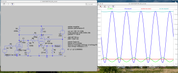
Thanks for your .asc file. I just gave it a spin, and it worked fine after the following mods:
1) I had to replace the LED by a 3V voltage source, because I don't have the spice model of your LED (BTW: Qspice makes the boring "don't have your spice model" problem obsolete - I love Qspice!!)
2) Same for the 12AX7 - Replaced it another one
3) I blanked out your "INC 6P13P.inc" command, and instead took the 6P13P spice model from #2672
So, perhaps it is worth to freshly integrate the model from #2672 into your sim?
BR Adrian
Attachments

Thanks alot Adrian, I have that same model in the INC file. I will try your mods when I’ll be back home.
I’ve never used QSpice, good to k ow there’s something else to simulate circuits!
I’ve never used QSpice, good to k ow there’s something else to simulate circuits!
347A SPICE Models

Code:
**** 347A ******************************************
* Created on 11/08/2024 16:50 using paint_kit.jar 3.1
* www.dmitrynizh.com/tubeparams_image.htm
* Plate Curves image file: 347A.jpg
* Data source link:
*----------------------------------------------------------------------------------
.SUBCKT TRIODE_347A 1 2 3 ; Plate Grid Cathode
+ PARAMS: CCG=2.3P  CGP=1.9P CCP=4.1P RGI=2000
+ MU=16.21 KG1=4320 KP=110 KVB=594 VCT=0.02713 EX=1.33
* Vp_MAX=300 Ip_MAX=6 Vg_step=2 Vg_start=0 Vg_count=9
* Rp=4000 Vg_ac=55 P_max=3.5 Vg_qui=-48 Vp_qui=300
* X_MIN=113 Y_MIN=135 X_SIZE=696 Y_SIZE=562 FSZ_X=1410 FSZ_Y=791 XYGrid=false
* showLoadLine=n showIp=y isDHT=n isPP=n isAsymPP=n showDissipLimit=y
* showIg1=n gridLevel2=n isInputSnapped=n
* XYProjections=n harmonicPlot=n dissipPlot=n
*----------------------------------------------------------------------------------
E1 7 0 VALUE={V(1,3)/KP*LOG(1+EXP(KP*(1/MU+(VCT+V(2,3))/SQRT(KVB+V(1,3)*V(1,3)))))}
RE1 7 0 1G  ; TO AVOID FLOATING NODES
G1 1 3 VALUE={(PWR(V(7),EX)+PWRS(V(7),EX))/KG1}
RCP 1 3 1G   ; TO AVOID FLOATING NODES
C1 2 3 {CCG} ; CATHODE-GRID
C2 2 1 {CGP} ; GRID=PLATE
C3 1 3 {CCP} ; CATHODE-PLATE
D3 5 3 DX ; POSITIVE GRID CURRENT
R1 2 5 {RGI} ; POSITIVE GRID CURRENT
.MODEL DX D(IS=1N RS=1 CJO=10PF TT=1N)
.ENDS348A SPICE Models
Code:
**** 348A ******************************************
* Created on 11/08/2024 17:44 using paint_kip.jar
* www.dmitrynizh.com/tubeparams_image.htm
* Plate Curves image file: 348A.jpg
* Data source link: <plate curves URL>
*----------------------------------------------------------------------------------
.SUBCKT 348A P G2 G K ; LTSpice tetrode.asy pinout
* .SUBCKT 348A P G K G2 ; Koren Pentode Pspice pinout
+ PARAMS: MU=18.4 KG1=4400 KP=349.87 KVB=5.94 VCT=0.12 EX=1.372 KG2=4242 KNEE=4.8 KVC=2.57
+ KLAM=5.8E-7 KLAMG=5.859E-8   KNK=-0.0983 KNG=0.006 KNPL=50 KNSL=10.67 KNPR=118.8 KNSR=28.42
+ CCG=6P CGP=15P CCP=0.025P RGI=2000.0
* Vp_MAX=280 Ip_MAX=12 Vg_step=1 Vg_start=0 Vg_count=8
* X_MIN=46 Y_MIN=104 X_SIZE=503 Y_SIZE=435 FSZ_X=1193 FSZ_Y=796 XYGrid=false
* Rp=1400 Vg_ac=20 P_max=2.5 Vg_qui=-3.5 Vp_qui=300
* showLoadLine=n showIp=y isDHP=n isPP=n isAsymPP=n isUL=n showDissipLimit=n
* showIg1=n isInputSnapped=y addLocalNFB=n
* XYProjections=n harmonicPlot=y dissipPlot=n
* UL=0.43 EG2=135 gridLevel2=n addKink=y isTanhKnee=n advSigmoid=n
*----------------------------------------------------------------------------------
RE1  7 0  1G    ; DUMMY SO NODE 7 HAS 2 CONNECTIONS
E1   7 0  VALUE=  ; E1 BREAKS UP LONG EQUATION FOR G1.
+{V(G2,K)/KP*LOG(1+EXP((1/MU+(VCT+V(G,K))/SQRT(KVB+V(G2,K)*V(G2,K)))*KP))}
RE2  6 0  1G    ; DUMMY SO NODE 6 HAS 2 CONNECTIONS
E2  6 0  VALUE={(PWR(V(7),EX)+PWRS(V(7),EX))} ; Kg1 times KIT current
RE21 21 0 1
E21  21 0 VALUE={V(6)/KG1*ATAN(V(P,K)/KNEE)} ; Ip with knee but no slope and no kink
RE22 22 0 1 ; E22: kink curr deviation for plate
E22  22 0 VALUE={V(21)*LIMIT(KNK-V(G,K)*KNG,0,0.3)*(-ATAN((V(P,K)-KNPL)/KNSL)+ATAN((V(P,K)-KNPR)/KNSR))}
G1   P  K  VALUE={V(21)*(1+KLAMG*V(P,K))+KLAM*V(P,K) + V(22)}
* Alexander Gurskii screen current, see audioXpress 2/2011, with slope and kink added
RE43 43 K 1G ; Dummy
E43  43 G2 VALUE={0} ; Dummy
G2   43 K  VALUE={V(6)/KG2*(KVC-ATAN(V(P,K)/KNEE))/(1+KLAMG*V(P,K))-V(22)}
RCP  P K  1G     ; FOR CONVERGENCE
C1   K G  {CCG}  ; CATHODE-GRID 1
C2   G P  {CGP}  ; GRID 1-PLATE
C3   K P  {CCP}  ; CATHODE-PLATE
R1   G 5  {RGI}  ; FOR GRID CURRENT
D3   5 K  DX     ; FOR GRID CURRENT }
.MODEL DX D(IS=1N RS=1 CJO=10PF TT=1N)
.ENDS
*$


* The following triode model is derived from pentode model, see above.
* In the triode model, all spice parameters come directly from the pentode model, except for Kg1,
* which for triode-strapped pentodes is derived from pentode's Kg1, Kg2 and Kvc as
*
*    4Kg1Kg2 / ((2Kvc-Pi)(2Kg1+PiKg2))

**** 348A ******************************************
* Created on 11/08/2024 17:44 using paint_kit.jar 4.7
* www.dmitrynizh.com/tubeparams_image.htm
* Plate Curves image file: 348A.jpg
* Data source link: <plate curves URL>
*----------------------------------------------------------------------------------
.SUBCKT TRIODE_348A 1 2 3 ; Plate Grid Cathode
+ PARAMS: CCG=6P  CGP=15P CCP=0.025P RGI=2000
+ MU=18.4 KG1=1688.44 KP=349.87 KVB=5.94 VCT=0.12 EX=1.372
* Vp_MAX=280 Ip_MAX=12 Vg_step=1 Vg_start=0 Vg_count=8
* Rp=1400 Vg_ac=20 P_max=2.5 Vg_qui=-3.5 Vp_qui=300
* X_MIN=46 Y_MIN=104 X_SIZE=503 Y_SIZE=435 FSZ_X=1193 FSZ_Y=796 XYGrid=false
* showLoadLine=n showIp=y isDHT=n isPP=n isAsymPP=n showDissipLimit=n
* showIg1=n gridLevel2=n isInputSnapped=y
* XYProjections=n harmonicPlot=y dissipPlot=n
*----------------------------------------------------------------------------------
E1 7 0 VALUE={V(1,3)/KP*LOG(1+EXP(KP*(1/MU+(VCT+V(2,3))/SQRT(KVB+V(1,3)*V(1,3)))))}
RE1 7 0 1G  ; TO AVOID FLOATING NODES
G1 1 3 VALUE={(PWR(V(7),EX)+PWRS(V(7),EX))/KG1}
RCP 1 3 1G   ; TO AVOID FLOATING NODES
C1 2 3 {CCG} ; CATHODE-GRID
C2 2 1 {CGP} ; GRID=PLATE
C3 1 3 {CCP} ; CATHODE-PLATE
D3 5 3 DX ; POSITIVE GRID CURRENT
R1 2 5 {RGI} ; POSITIVE GRID CURRENT
.MODEL DX D(IS=1N RS=1 CJO=10PF TT=1N)
.ENDS
*$
Attachments
EL83 / PL83 / 6CK6 / 15A6 / N309 LTSpice models request
Gentlemen,
I would like to draw your attention to type EL83 / PL83 / 6CK6 / 15A6 / N309 (there also are at least two Russian substitution types). Unfortunally I can´t find any LTSpice models for it.
This is a very linear and sensitive video wideband amplifier used in millions of European TV sets. Especially its 300 mA series heater version PL83 / 15A6 still can be found plentiful and cheap in Europe. Quite some datasheets can be found @ frank.pocnet.net
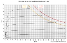
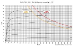
Please note that this valve was made both as a true pentode and as beam power tetrode, the later version being much more common. For practical purposes they are interchangeable, but the plots are noticably different at low anode voltages (see the Marconi N309 sheet for true pentode curves).
In most datasheets, plots for the BPT type can be found, usually given for Eg2 = 170, 200 and 220 Volts. To give the community something back I also attached my own plots at Eg2 = 125V and 150V.
A triode strapped plot can be found in the Marconi N309 data sheet.
Besides using it as a final stage audio output tube, please note that this valve makes an extremely capable and linear pentode driver for much bigger output tubes, see load line example attached.
I would be happy if somebody could supply LTSpice models for the (much more common) BPT type and also in triode strapped operation
Thank you very much!
Tom
Gentlemen,
I would like to draw your attention to type EL83 / PL83 / 6CK6 / 15A6 / N309 (there also are at least two Russian substitution types). Unfortunally I can´t find any LTSpice models for it.
This is a very linear and sensitive video wideband amplifier used in millions of European TV sets. Especially its 300 mA series heater version PL83 / 15A6 still can be found plentiful and cheap in Europe. Quite some datasheets can be found @ frank.pocnet.net
Please note that this valve was made both as a true pentode and as beam power tetrode, the later version being much more common. For practical purposes they are interchangeable, but the plots are noticably different at low anode voltages (see the Marconi N309 sheet for true pentode curves).
In most datasheets, plots for the BPT type can be found, usually given for Eg2 = 170, 200 and 220 Volts. To give the community something back I also attached my own plots at Eg2 = 125V and 150V.
A triode strapped plot can be found in the Marconi N309 data sheet.
Besides using it as a final stage audio output tube, please note that this valve makes an extremely capable and linear pentode driver for much bigger output tubes, see load line example attached.
I would be happy if somebody could supply LTSpice models for the (much more common) BPT type and also in triode strapped operation
Thank you very much!
Tom
Attachments
There is an Ayumi model:
Code:
*
* Generic pentode model: EL83
* Copyright 2003--2008 by Ayumi Nakabayashi, All rights reserved.
* Version 3.10, Generated on Fri Sep 18 10:19:14 2015
*                Plate
*                | Screen Grid
*                | |  Control Grid
*                | |  |  Cathode
*                | |  |  |
.SUBCKT EL83 A G2 G1 K
BGG   GG   0 V=V(G1,K)+-0.58288162
BM1   M1   0 V=(0.027878725*(URAMP(V(G2,K))+1e-10))**-1.1736118
BM2   M2   0 V=(0.56103882*(URAMP(V(GG)+URAMP(V(G2,K))/15.745382)))**2.6736118
BP    P    0 V=0.0078884298*(URAMP(V(GG)+URAMP(V(G2,K))/28.064693))**1.5
BIK   IK   0 V=U(V(GG))*V(P)+(1-U(V(GG)))*0.005914561*V(M1)*V(M2)
BIG   IG   0 V=0.0039442149*URAMP(V(G1,K))**1.5*(URAMP(V(G1,K))/(URAMP(V(A,K))+URAMP(V(G1,K)))*1.2+0.4)
BIK2  IK2  0 V=V(IK,IG)*(1-0.4*(EXP(-URAMP(V(A,K))/URAMP(V(G2,K))*15)-EXP(-15)))
BIG2T IG2T 0 V=V(IK2)*(0.87412329*(1-URAMP(V(A,K))/(URAMP(V(A,K))+10))**1.5+0.12587671)
BIK3  IK3  0 V=V(IK2)*(URAMP(V(A,K))+4012.5)/(URAMP(V(G2,K))+4012.5)
BIK4  IK4  0 V=V(IK3)-URAMP(V(IK3)-(0.004369569*(URAMP(V(A,K))+URAMP(URAMP(V(G2,K))-URAMP(V(A,K))))**1.5))
BIP   IP   0 V=URAMP(V(IK4,IG2T)-URAMP(V(IK4,IG2T)-(0.004369569*URAMP(V(A,K))**1.5)))
BIAK  A    K I=V(IP)+1e-10*V(A,K)
BIG2  G2   K I=URAMP(V(IK4,IP))
BIGK  G1   K I=V(IG)
* CAPS
CGA   G1  A  0.07p
CGK   G1  K  8.4p
C12   G1  G2 5.6p
CAK   A   K  8p
.ENDSHere are both pentode and triode-connected models for the 6P15P.
6P15P SPICE Models
Pentode
Pentode
Code:
*
* Generic pentode model: 6P15P_AN
* Copyright 2003--2008 by Ayumi Nakabayashi, All rights reserved.
* Version 3.10, Generated on Fri Sep 18 10:19:14 2015
*                Plate
*                | Screen Grid
*                | |  Control Grid
*                | |  |  Cathode
*                | |  |  |
.SUBCKT 6P15P_AN A G2 G1 K
BGG   GG   0 V=V(G1,K)+-0.58288162
BM1   M1   0 V=(0.027878725*(URAMP(V(G2,K))+1e-10))**-1.1736118
BM2   M2   0 V=(0.56103882*(URAMP(V(GG)+URAMP(V(G2,K))/15.745382)))**2.6736118
BP P 0...Ray and jcalvarez, thank you very much for the EL83 models!
BTW, before asking here, I had a look at the Ayumi models archive file "tubemodel_3.20_win.zip", but that one didn´t contain the EL83 model. So it looks like there are Ayumi models out in the wild which are not contained in that archieve. Any hints where to find them?
Thank you very much and kind regards, Tom
These two models have the same date and time and appear to be the same except for the last line in the second model and the second model's missing .ENDS statement. They are both pentode (actually tetrode) models.
Ayumi did produce both pentode and triode-connected models for the 12BY7A. Both are shown below.
Pentode Model:
Code:* * Generic pentode model: 12BY7A * Copyright 2003--2008 by Ayumi Nakabayashi, All rights reserved. * Version 3.10, Generated on Sat Mar 8 22:41:15 2008 * Plate * | Screen Grid * | | Control Grid * | | | Cathode * | | | | .SUBCKT 12BY7A A G2 G1 K BGG GG 0 V=V(G1,K)+-0.02185341 BM1 M1 0 V=(0.014593712*(URAMP(V(G2,K))+1e-10))**-0.7027291 BM2 M2 0 V=(0.68097344*(URAMP(V(GG)+URAMP(V(G2,K))/21.860549)))**2.2027291 BP P 0 V=0.0061475247*(URAMP(V(GG)+URAMP(V(G2,K))/32.101912))**1.5 BIK IK 0 V=U(V(GG))*V(P)+(1-U(V(GG)))*0.0036081888*V(M1)*V(M2) BIG IG 0 V=0.0030737623*URAMP(V(G1,K))**1.5*(URAMP(V(G1,K))/(URAMP(V(A,K))+URAMP(V(G1,K)))*1.2+0.4) BIK2 IK2 0 V=V(IK,IG)*(1-0.4*(EXP(-URAMP(V(A,K))/URAMP(V(G2,K))*15)-EXP(-15))) BIG2T IG2T 0 V=V(IK2)*(0.82512147*(1-URAMP(V(A,K))/(URAMP(V(A,K))+10))**1.5+0.17487853) BIK3 IK3 0 V=V(IK2)*(URAMP(V(A,K))+4890)/(URAMP(V(G2,K))+4890) BIK4 IK4 0 V=V(IK3)-URAMP(V(IK3)-(0.0033632383*(URAMP(V(A,K))+URAMP(URAMP(V(G2,K))-URAMP(V(A,K))))**1.5)) BIP IP 0 V=URAMP(V(IK4,IG2T)-URAMP(V(IK4,IG2T)-(0.0033632383*URAMP(V(A,K))**1.5))) BIAK A K I=V(IP)+1e-10*V(A,K) BIG2 G2 K I=URAMP(V(IK4,IP)) BIGK G1 K I=V(IG) * CAPS CGA G1 A 0.063p CGK G1 K 6.1p C12 G1 G2 4.1p CAK A K 3.4p .ENDS
Triode-Connected Model:
Code:* * Generic triode model: 12BY7AT * Copyright 2003--2008 by Ayumi Nakabayashi, All rights reserved. * Version 3.10, Generated on Sat Mar 8 22:41:15 2008 * Plate * | Grid * | | Cathode * | | | .SUBCKT 12BY7AT A G K BGG GG 0 V=V(G,K)+-0.02185341 BM1 M1 0 V=(0.014593712*(URAMP(V(A,K))+1e-10))**-0.7027291 BM2 M2 0 V=(0.68097344*(URAMP(V(GG)+URAMP(V(A,K))/21.860549)+1e-10))**2.2027291 BP P 0 V=0.0061475247*(URAMP(V(GG)+URAMP(V(A,K))/32.101912)+1e-10)**1.5 BIK IK 0 V=U(V(GG))*V(P)+(1-U(V(GG)))*0.0036081888*V(M1)*V(M2) BIG IG 0 V=0.0030737623*URAMP(V(G,K))**1.5*(URAMP(V(G,K))/(URAMP(V(A,K))+URAMP(V(G,K)))*1.2+0.4) BIAK A K I=URAMP(V(IK,IG)-URAMP(V(IK,IG)-(0.0033632383*URAMP(V(A,K))**1.5)))+1e-10*V(A,K) BIGK G K I=V(IG) * CAPS CGA G A 4.1p CGK G K 6.1p CAK A K 3.4p .ENDS
I can't seem to get this model to work, is there something i need to be aware of in running them on LTspice, unlike other models?
There is nothing special about the triode-connected model. Just use the built-in triode symbol with it.
The "pentode" model is actually a tetrode (it doesn't model the suppressor grid) so use the built-in tetrode symbol instead of the pentode symbol.
Again, nothing special needs to be done to use these models with LTspice. The models are already formatted for LTspice (the ^ character has been replaced with **, which LTspice requires).
Maybe if you post your .asc files someone can help figure out what is wrong.
Problem wih both, triode and tetrode ?
Does not sound like its the model, rather circuit.
Or drawing. I remember that when you replace tetrode with triode symbol, that leaves a gap in the plate wire, because triode symbol is shorter.
Anyway if you post your .asc file (zipped or renamed .txt) I am willing to have a look.
Does not sound like its the model, rather circuit.
Or drawing. I remember that when you replace tetrode with triode symbol, that leaves a gap in the plate wire, because triode symbol is shorter.
Anyway if you post your .asc file (zipped or renamed .txt) I am willing to have a look.
I plugged both of these models into circuits which plot their characteristic curves and both worked fine. So here is a third request for you to post your LTspice .asc files. Without those to look at, it's doubtful that anyone here will be able to help you.sorry I didnt leave more details. I just get no conduction. 0mv across the tube plate. unlike other models.
I only have issues with some tetrodes, i suspect its got to do with the plate getting demarcated as a "P" or a "a" in the model
Also, i seem to read that it might be because i am using an old version of LTSpice or what was then called SwCad. is that the reason?
Also, i seem to read that it might be because i am using an old version of LTSpice or what was then called SwCad. is that the reason?
Last edited:
* C:\Program Files\LTC\LTspiceIV\6ge5_outputstage.asc
L1 N001 b+ 13.36 Rser=200
L2 b+ N008 13.36 Rser=200
L3 N003 0 .067
V1 b+ 0 450
R1 N003 0 8
V2 vs 0 200
R2 N002 0 10k
R3 0 N006 10k
V3 b 0 -42
L4 N002 b 21
L5 b N006 21
XU3 N004 N005 N007 6e6p
R4 N007 0 200
V4 N005 0 SINE(0 1 1000)
C1 N007 0 470µ
L6 vs N004 21
XU1 N001 vs N002 0 6EW6
XU2 N008 vs N006 0 6EW6
KALL L1 L2 L3 0.999332925685523
.tran 0 .04 .02
.fourier 1000 V(n003)
.MEAS TRAN V(n003)*I(R1)
K L6 L4 L5 0.999332925685523
.lib tubes.sub
.backanno
.end
If you note XU1 and XU2, seems no matter what i do, the 4th pin is always 0, even if i put a resistor there.
do you see a ground symbol connected in your schematic entry ?
when missing not always error flagged in LTspice ...
when missing not always error flagged in LTspice ...
Maybe it's just me, but I always get a warning from LTspice when I inadvertently leave out the signal ground. I doubt that this is the problem.
The issue I'm having is that the OP still has not uploaded his actual .asc file so no one can run a simulation for themselves. What was posted in message #3977 is a net list, not the text of an .asc file, which has a completely different syntax.
The issue I'm having is that the OP still has not uploaded his actual .asc file so no one can run a simulation for themselves. What was posted in message #3977 is a net list, not the text of an .asc file, which has a completely different syntax.
yup, i have a ground, across multiple components, it reflects as a 0 on the netlist.do you see a ground symbol connected in your schematic entry ?
when missing not always error flagged in LTspice ...
- Home
- Amplifiers
- Tubes / Valves
- Vacuum Tube SPICE Models