6gn8 pentode model, try it , while i model triode section:
.SUBCKT 6GN8 P G2 G K ; LTSpice tetrode.asy pinout
* .SUBCKT 6GN8 P G K G2 ; Koren Pentode Pspice pinout
- PARAMS: MU=27.1 KG1=589.05 KP=105.29 KVB=12 VCT=0.2 EX=1.4 KG2=523.91 KNEE=27.71 KVC=1.811
- KLAM=2.225E-8 KLAMG=3.282E-4 KNEE2=17.44 KNEX=82.8 KNK=7.813E-4 KNG=0.04312 KNPL=1.281 KNSL=0.06875 KNPR=69.6 KNSR=32.48
- CCG=11P CGP=0.1P CCP=4.2P VGOFF=-0.6 IGA=0.001 IGB=0.3 IGC=8 IGEX=2
*----------------------------------------------------------------------------------
- Vp_MAX=400 Ip_MAX=80 Vg_step=1 Vg_start=0 Vg_count=20
- X_MIN=39 Y_MIN=106 X_SIZE=754 Y_SIZE=478 FSZ_X=1296 FSZ_Y=736 XYGrid=false
- Rp=1400 Vg_ac=20 P_max=5 Vg_qui=-9.5 Vp_qui=300
- showLoadLine=n showIp=y isDHP=n isPP=n isAsymPP=n isUL=n showDissipLimit=y
- showIg1=y isInputSnapped=y addLocalNFB=n
- XYProjections=n harmonicPlot=y dissipPlot=n
- UL=0.43 EG2=150 gridLevel2=y addKink=y isTanhKnee=y advSigmoid=n
RE1 7 0 1G ; DUMMY SO NODE 7 HAS 2 CONNECTIONS
E1 7 0 VALUE= ; E1 BREAKS UP LONG EQUATION FOR G1.
+{V(G2,K)/KP*LOG(1+EXP((1/MU+(VCT+V(G,K))/SQRT(KVB+V(G2,K)*V(G2,K)))*KP))}
RE2 6 0 1G ; DUMMY SO NODE 6 HAS 2 CONNECTIONS
E2 6 0 VALUE={(PWR(V(7),EX)+PWRS(V(7),EX))} ; Kg1 times KIT current
RE21 21 0 1
E21 21 0 VALUE={V(6)/KG1*ATAN((V(P,K)+KNEX)/KNEE)*TANH(V(P,K)/KNEE2)} ; Ip with knee but no slope and no kink
RE22 22 0 1 ; E22: kink curr deviation for plate
E22 22 0 VALUE={V(21)LIMIT(KNK-V(G,K)*KNG,0,0.3)(-ATAN((V(P,K)-KNPL)/KNSL)+ATAN((V(P,K)-KNPR)/KNSR))}
G1 P K VALUE={V(21)*(1+KLAMG*V(P,K))+KLAM*V(P,K) + V(22)}
* Alexander Gurskii screen current, see audioXpress 2/2011, with slope and kink added
RE43 43 K 1G ; Dummy
E43 43 G2 VALUE={0} ; Dummy
G2 43 K VALUE={V(6)/KG2*(KVC-ATAN((V(P,K)+KNEX)/KNEE)*TANH(V(P,K)/KNEE2))/(1+KLAMG*V(P,K))-V(22)}
RCP P K 1G ; FOR CONVERGENCE
C1 K G {CCG} ; CATHODE-GRID 1
C2 G P {CGP} ; GRID 1-PLATE
C3 K P {CCP} ; CATHODE-PLATE
RE23 G 0 1G
GG G K VALUE={(IGA+IGB/(IGC+V(P,K)))(MU/KG1)
+(PWR(V(G,K)-VGOFF,IGEX)+PWRS(V(G,K)-VGOFF,IGEX))}
.ENDS
*$
Attachments
6gn8 triode section model:
** 6GN8T ** Advanced Grid Current ********************************
*----------------------------------------------------------------------------------
- Created on 01/19/2022 17:50 using paint_kit.jar 3.1
- www.dmitrynizh.com/tubeparams_image.htm
- Plate Curves image file: 6gn8t.png
- Data source link:
.SUBCKT 6GN8T 1 2 3 ; Plate Grid Cathode
- PARAMS: CCG=2.4P CGP=4.4P CCP=0.36P
- MU=100 KG1=750 KP=460 KVB=1320 VCT=0.282 EX=1.4
- VGOFF=-0.6 IGA=1.8E-4 IGB=0.138 IGC=10 IGEX=1.04
*----------------------------------------------------------------------------------
- Vp_MAX=400 Ip_MAX=25 Vg_step=1 Vg_start=0 Vg_count=5
- Rp=4000 Vg_ac=55 P_max=1 Vg_qui=-48 Vp_qui=300
- X_MIN=37 Y_MIN=99 X_SIZE=765 Y_SIZE=478 FSZ_X=1296 FSZ_Y=736 XYGrid=false
- showLoadLine=n showIp=y isDHT=n isPP=n isAsymPP=n showDissipLimit=y
- showIg1=y gridLevel2=y isInputSnapped=n
- XYProjections=n harmonicPlot=n dissipPlot=n
E1 7 0 VALUE={V(1,3)/KP*LOG(1+EXP(KP*(1/MU+(VCT+V(2,3))/SQRT(KVB+V(1,3)*V(1,3)))))}
RE1 7 0 1G ; TO AVOID FLOATING NODES
G1 1 3 VALUE={(PWR(V(7),EX)+PWRS(V(7),EX))/KG1}
RCP 1 3 1G ; TO AVOID FLOATING NODES
C1 2 3 {CCG} ; CATHODE-GRID
C2 2 1 {CGP} ; GRID=PLATE
C3 1 3 {CCP} ; CATHODE-PLATE
RE2 2 0 1G
EGC 8 0 VALUE={V(2,3)-VGOFF} ; POSITIVE GRID THRESHOLD
GG 2 3 VALUE={(IGA+IGB/(IGC+V(1,3)))(MU/KG1)(PWR(V(8),IGEX)+PWRS(V(8),IGEX))}
.ENDS
*$
Attachments

Code:
**** 6GN8 ******************************************
* Created on 01/19/2022 17:10 using paint_kip.jar
* www.dmitrynizh.com/tubeparams_image.htm
* Plate Curves image file: 6gn8.png
* Data source link: <plate curves URL>
*----------------------------------------------------------------------------------
.SUBCKT 6GN8 P G2 G K ; LTSpice tetrode.asy pinout
* .SUBCKT 6GN8 P G K G2 ; Koren Pentode Pspice pinout
+ PARAMS: MU=27.1 KG1=589.05 KP=105.29 KVB=12 VCT=0.2 EX=1.4 KG2=523.91 KNEE=27.71 KVC=1.811
+ KLAM=2.225E-8 KLAMG=3.282E-4 KNEE2=17.44 KNEX=82.8  KNK=7.813E-4 KNG=0.04312 KNPL=1.281 KNSL=0.06875 KNPR=69.6 KNSR=32.48
+ CCG=11P CGP=0.1P CCP=4.2P VGOFF=-0.6 IGA=0.001 IGB=0.3 IGC=8 IGEX=2
* Vp_MAX=400 Ip_MAX=80 Vg_step=1 Vg_start=0 Vg_count=20
* X_MIN=39 Y_MIN=106 X_SIZE=754 Y_SIZE=478 FSZ_X=1296 FSZ_Y=736 XYGrid=false
* Rp=1400 Vg_ac=20 P_max=5 Vg_qui=-9.5 Vp_qui=300
* showLoadLine=n showIp=y isDHP=n isPP=n isAsymPP=n isUL=n showDissipLimit=y
* showIg1=y isInputSnapped=y addLocalNFB=n
* XYProjections=n harmonicPlot=y dissipPlot=n
* UL=0.43 EG2=150 gridLevel2=y addKink=y isTanhKnee=y advSigmoid=n
*----------------------------------------------------------------------------------
RE1  7 0  1G    ; DUMMY SO NODE 7 HAS 2 CONNECTIONS
E1   7 0  VALUE=  ; E1 BREAKS UP LONG EQUATION FOR G1.
+{V(G2,K)/KP*LOG(1+EXP((1/MU+(VCT+V(G,K))/SQRT(KVB+V(G2,K)*V(G2,K)))*KP))}
RE2  6 0  1G    ; DUMMY SO NODE 6 HAS 2 CONNECTIONS
E2  6 0  VALUE={(PWR(V(7),EX)+PWRS(V(7),EX))} ; Kg1 times KIT current
RE21 21 0 1
E21  21 0 VALUE={V(6)/KG1*ATAN((V(P,K)+KNEX)/KNEE)*TANH(V(P,K)/KNEE2)} ; Ip with knee but no slope and no kink
RE22 22 0 1 ; E22: kink curr deviation for plate
E22  22 0 VALUE={V(21)*LIMIT(KNK-V(G,K)*KNG,0,0.3)*(-ATAN((V(P,K)-KNPL)/KNSL)+ATAN((V(P,K)-KNPR)/KNSR))}
G1   P  K  VALUE={V(21)*(1+KLAMG*V(P,K))+KLAM*V(P,K) + V(22)}
* Alexander Gurskii screen current, see audioXpress 2/2011, with slope and kink added
RE43 43 K 1G ; Dummy
E43  43 G2 VALUE={0} ; Dummy
G2   43 K  VALUE={V(6)/KG2*(KVC-ATAN((V(P,K)+KNEX)/KNEE)*TANH(V(P,K)/KNEE2))/(1+KLAMG*V(P,K))-V(22)}
RCP  P K  1G     ; FOR CONVERGENCE
C1   K G  {CCG}  ; CATHODE-GRID 1
C2   G P  {CGP}  ; GRID 1-PLATE
C3   K P  {CCP}  ; CATHODE-PLATE
RE23 G 0 1G
GG G K VALUE={(IGA+IGB/(IGC+V(P,K)))*(MU/KG1)*
+(PWR(V(G,K)-VGOFF,IGEX)+PWRS(V(G,K)-VGOFF,IGEX))}
.ENDS
*$
Code:
**** 6GN8T ** Advanced Grid Current **********************************
* Created on 01/19/2022 17:50 using paint_kit.jar 3.1
* www.dmitrynizh.com/tubeparams_image.htm
* Plate Curves image file: 6gn8t.png
* Data source link:
*----------------------------------------------------------------------------------
.SUBCKT 6GN8T 1 2 3 ; Plate Grid Cathode
+ PARAMS: CCG=2.4P CGP=4.4P CCP=0.36P
+ MU=100 KG1=750 KP=460 KVB=1320 VCT=0.282 EX=1.4
+ VGOFF=-0.6 IGA=1.8E-4 IGB=0.138 IGC=10 IGEX=1.04
* Vp_MAX=400 Ip_MAX=25 Vg_step=1 Vg_start=0 Vg_count=5
* Rp=4000 Vg_ac=55 P_max=1 Vg_qui=-48 Vp_qui=300
* X_MIN=37 Y_MIN=99 X_SIZE=765 Y_SIZE=478 FSZ_X=1296 FSZ_Y=736 XYGrid=false
* showLoadLine=n showIp=y isDHT=n isPP=n isAsymPP=n showDissipLimit=y
* showIg1=y gridLevel2=y isInputSnapped=n
* XYProjections=n harmonicPlot=n dissipPlot=n
*----------------------------------------------------------------------------------
E1 7 0 VALUE={V(1,3)/KP*LOG(1+EXP(KP*(1/MU+(VCT+V(2,3))/SQRT(KVB+V(1,3)*V(1,3)))))}
RE1 7 0 1G ; TO AVOID FLOATING NODES
G1 1 3 VALUE={(PWR(V(7),EX)+PWRS(V(7),EX))/KG1}
RCP 1 3 1G ; TO AVOID FLOATING NODES
C1 2 3 {CCG} ; CATHODE-GRID
C2 2 1 {CGP} ; GRID=PLATE
C3 1 3 {CCP} ; CATHODE-PLATE
RE2 2 0 1G
EGC 8 0 VALUE={V(2,3)-VGOFF} ; POSITIVE GRID THRESHOLD
GG 2 3 VALUE={(IGA+IGB/(IGC+V(1,3)))*(MU/KG1)*(PWR(V(8),IGEX)+PWRS(V(8),IGEX))}
.ENDS
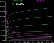
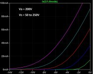
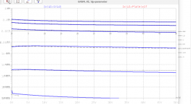
*$that's great Koonw, much appreciated and thanks for the quick turnaround. The results look good, for different screen voltages anode current vs anode and grid voltage look similar to the data sheet.
Attachments
Dear diyaudio members
Please note my latest i5 model for the 6AM4. It is a very potent triode, with one of the highest gm*mu value I have ever seen. A drawback may be that this tube isn't very linear...
All the best, Adrian
Please note my latest i5 model for the 6AM4. It is a very potent triode, with one of the highest gm*mu value I have ever seen. A drawback may be that this tube isn't very linear...
All the best, Adrian
Code:
*6AM4 LTspice model based on the generic triode model from Adrian Immler, version i5
*A version log is at the end of this file
*100h BurnIn of 10 tubes, sample selection and measurements done in Dec 2021
*Params fitted to the measured values by Adrian Immler, Jan 2022
*The high fit quality is presented at adrianimmler.simplesite.com
*History's best of tube decribing art (plus some new ideas) is merged to this new approach.
*@ neg. Vg, Ia accuracy is similar to Koren models, and unrivaled for remote cutoff triodes
*@ small neg. Vg, the "Anlauf" current is considered.
*@ pos. Vg, Ig and Ia accuracy is on a unrivaled level (including neg. Va range!)
*This offers new simulation possibilities like grid resistor bias, backward plate modulated stages,
*Audion radio circuits, low voltage amps, guitar distortion stages or pulsed stages.
*            all 6AM4s seen share the same construction (so, no company letters needed)
*            |  anode (plate)
*            |  | grid
*            |  | | cathode
*            |  | | |
.subckt 6AM4.i5 A G K
+ params:
*Parameters for space charge current Is (100% assigned to Ia @ Vg < 0)
+ mu   = 125   ;Determines the voltage gain @ constant Ia
+ rad  = 10k1  ;Differential anode resistance, set @ Iad and Vg=0V
+ Vct  = 0.05  ;Offsets the Ia-traces on the Va axis. Electrode material's contact potential
+ kp   = 302   ;Mimics the island effect
+ xs   = 1.5   ;Determines the curve of the Ia traces. Typically between 1.2 and 1.8
+ kIsr = 70m   ;Va-indepedent part of the Is reduction when gridcurrent occurs
+ kvdg  = 75   ;Va-depedent part of the Is reduction when gridcurrent occurs
*
*Parameters for assigning the space charge current to Ia and Ig @ Vg > 0
+ kB   = 0.14  ;Describes how fast Ia drops to zero when Va approaches zero.
+ radl = 100   ;Differential resistance for the Ia emission limit @ very small Va and Vg > 0
+ tsh  = 20    ;Ia transmission sharpness from 1th to 2nd Ia area. Keep between 3 and 20. Start with 20.
+ xl   = 1.2   ;Exponent for the emission limit
*
*Parameters of the grid-cathode vacuum diode
+ kg = 263     ;Inverse scaling factor for the Va independent part of Ig (caution - interacts with xg!)
+ Vctg = -0.3  ;Offsets the log Ig-traces on the Vg axis. Electrode material's contact potential
+ xg   = 1.4   ;Determines the curve of the Ig slope versus (positive) Vg and Va >> 0
+ VT   = 0.10  ;Log(Ig) slope @ Vg<0. VT=k/q*Tk (cathodes absolute temp, typically 1150K)
+ rTr  = 0.83  ;ratio of VT for Igr. Typically 0.8
+ kVT  = 0     ;Va dependant koeff. of VT
+ gft1 = 0.03  ;reduces the steering voltage around Vg=-Vg0, for finetuning purposes
+ gft1a= 0.2   ;reduces the steering voltage around Vg=-Vg0. Effect decreases with 1/(1+kB*Va)
+ gft2 = 0     ;finetunes the Igr drop @ incrasing Va and around Vg=-Vg0
*
*Parameters for the caps
+ cag  = 2p4   ;From GE datasheet
+ cak  = 0p16  ;From GE datasheet
+ cgk  = 4p4   ;From GE datasheet
*
*special purpose parameters
+ os = 1       ;Overall scaling factor, if a user wishes to simulate manufacturing tolerances
+ murc = 10    ;Mu of the remote cutoff triode
+ ksrc = 10G   ;Inverse Iarc gain factor for the remote cuttoff triode
+ kprc = 1k    ;Mimics the island effect for the remote cotoff triode
+ Vbatt = 0    ;heater battery voltage for direct heated battery triodes
+ Vdrmax = 100 ;max voltage of internal Vg drop, for convergence improvements
*
*Calculated parameters
+ Iad = {100/rad} ;Ia where the anode a.c. resistance is set according to rad.
+ ks = {pow(mu/(rad*xs*Iad**(1-1/xs)),-xs)} ;Reduces the unwished xs influence to the Ia slope
+ ksnom = {pow(mu/(rad*1.5*Iad**(1-1/1.5)),-1.5)} ;Sub-equation for calculating Vg0
+ Vg0 = {Vct + (Iad*ks)**(1/xs) - (Iad*ksnom)**(2/3)} ;Reduces the xs influence to Vct.
+ kl = {pow(1/(radl*xl*Ild**(1-1/xl)),-xl)} ;Reduces the xl influence to the Ia slope @ small Va
+ Ild = {sqrt(radl)*1m} ;Current where the Il a.c. resistance is set according to radl.
*
*Space charge current model
Rak A K 100G ;avoids "floating net" errors
Bft   ft 0 V=1/(1+pow(2*abs(v(G,Ki)+Vg0),3)) ;an auxiliary voltage to finetune the triode around Vg=-Vg0
Bggi GGi 0 V=(v(Gi,Ki)+Vg0)*(1/(1+kIsr*max(0, v(G,Ki)+Vg0))) - gft1*v(ft) - gft1a*v(ft)/(1+kB*v(Ahc)) ;Effective internal grid voltage.
Bahc Ahc 0 V=uramp(v(A,Ki)) ;Anode voltage, hard cut to zero @ neg. value
Bst   St 0 V=uramp(max(v(GGi)+v(A,Ki)/(mu), v(A,Ki)/kp*ln(1+exp(kp*(1/mu+v(GGi)/(1+v(Ahc)))))));Steering volt.
Bs    Ai Ki I=os/ks*pow(v(St),xs) ;Langmuir-Childs law for the space charge current Is
*Bstrc Strc 0 V=uramp(max(v(GGi)+v(Ahc)/(murc), v(Ahc)/kprc*ln(1+exp(kprc*(1/murc+v(GGi)/(1+v(Ahc)))))));FOR REMOTE CUTOFF TUBES ONLY
*Bsrc   Ai Ki I=os/ksrc*pow(v(Strc),xs) ;FOR REMOTE CUTOFF TUBES ONLY
*
*Anode current limit @ small Va
.func smin(z,y,k) {pow(pow(z+1f, -k)+pow(y+1f, -k), -1/k)} ;Min-function with smooth trans.
.func ssmin(z,y,k) {min(min(z,y), smin(z*1.003,y*1.003,k))};smin-function which suppresses small residual differencies
Ra  A Ai 1
Bgl Gi A I=uramp(i(Ra)-ssmin(1/kl*pow(v(Ahc),xl),i(Ra),tsh)) ;Ia emission limit
*
*Grid model
Rgk G K 10G ;avoids "floating net" errors
Bvdg G Gi I=1/kvdg*pow(v(G,Gi),1.5) ;Reduces the internal effective grid voltage when Ig rises
Bcoh G Gi I=pow(uramp(v(G,Gi)-Vdrmax),2) ;A convergence help which softly limits the internal Vg voltage drop.
Rgip G Gi 1G ;avoids some warnings
.func fVT() {VT*exp(-kVT*sqrt(v(A,Ki)))}
.func Ivd(Vvd, kvd, xvd, VTvd)  {if(Vvd < 3, 1/kvd*pow(VTvd*xvd*ln(1+exp(Vvd/VTvd/xvd)),xvd), 1/kvd*pow(Vvd, xvd))} ;Vacuum diode function
Bgvd G Ki I=Ivd(v(G,Ki) + Vctg + min(0,v(A,Ki)/mu), kg/os, xg, fVT()) ;limits the internal Vg for convergence reasons
Bstn Stn 0 V=v(GGi)+min(0,v(A,Ki))/mu ;special steering voltage, sensitive to negative Anodevoltages only
Bgr Gi Ai I= ivd(v(Stn),ks/os, xs, rTr*fVT())/(1+(kB+v(ft)*gft2)*v(Ahc));Is reflection to grid when Va approaches zero
*Bgr Gi Ai I=(ivd(v(Stn),ks/os, xs, rTr*fVT())+os/ksrc*pow(v(GGi),xs))/(1+(kB+v(ft)*gft2)*v(Ahc));FOR REMOTE CUTOFF TUBES ONLY
Bs0 Ai Ki  I=uramp(ivd(v(Stn),ks/os, xs, rTr*fVT()) - os/ks*pow(v(Stn),xs))
Bbatt Ki K V=Vbatt/2 ;for battery heated triodes; Offsets the average cathode potential to the half heater battery voltage
*
*Caps
C1 A G {cag}
C2 A K {cak}
C3 G K {cgk}
.ends
*
*Version log
*i1 :Initial version
*i2 :Pin order changed to the more common order A G K (Thanks to Markus Gyger for his tip)
*i3 :bugfix of the Ivd-function: now also usable for larger Vvd
*i4: Rgi replaced by a virtual vacuum diode (better convergence). ft1 deleted (no longer needed)
;2 new prarams for Ig finetuning @ Va and Vg near zero. New overall skaling factor os for aging etc.
*i5: improved convergence performance. PosVg/NegVa area now correct. Also accurate now for remote cutoff triodes!
Attachments
Hi Adrian,Please note my latest i5 model for the 6AM4.
Are you sure, that all parameter is correct?
In the datasheet -1V, 10mA op. point at about 200V.

BTW this tube (at small swing) suitable for phono.
Vinylsavor tried it.
Hi euro21
Yes, I'm pretty sure that all parameters are set correctly.
The point is that you refer to a datasheet, while this model is based on measured curves.
My steps:
It's up to you what you think is closer to reality - the datasheet or my golden sample 😉
BR Adrian
Yes, I'm pretty sure that all parameters are set correctly.
The point is that you refer to a datasheet, while this model is based on measured curves.
My steps:
- I took 10 tubes,
- burnt them all in for 100h at 2/3 of the max. allowed plate power,
- measured them all with my iTracer
- selected the most representative tube regarding mu, gm, contact voltage, island effect and grid current
- fitted a generic i5 model to the curves of this golden sample. The fit is well done as you can see in my graphs in #3186
It's up to you what you think is closer to reality - the datasheet or my golden sample 😉
BR Adrian
Yes, I think so. The high gm is promising regarding noise. And the high mu is anyway wished, as phono delivers small signals only.BTW this tube (at small swing) suitable for phono.
Vinylsavor tried it.
Your model is very correct ... but the Vg consistently shifted to the right by 0.5V.the datasheet or my golden sample 😉
BR Adrian
What shall I say?
The more I measure burntin tubes, the less I see tube datasheet curves as something you can relay on... 🤔
Especially for the Russian triodes, a datasheet graph is not more than a rough indication.
BR Adrian
The more I measure burntin tubes, the less I see tube datasheet curves as something you can relay on... 🤔
Especially for the Russian triodes, a datasheet graph is not more than a rough indication.
BR Adrian
I believe the datasheet ... exceeding by 23 percent (as in simulation) the 2W dissipation limit not a good omen. 🙂

6AM4 does look like a good candidate for use in a phono stage, but that Cag of 2.4pF is higher than some other triodes. The mu of 85 (probably more like 65 or so in a real life circuit) and that high of Cag will make input capacitance very high, That will upset SUTs and MM cartridges. Otherwise, 6AM4 looks great.
Sounds like a contest. Why don't you build the circuit, measure it, and then see whether the measured numbers are closer to the datasheet or Adrian's SPICE model?I believe the datasheet ... exceeding by 23 percent (as in simulation) the 2W dissipation limit not a good omen.
Currently i don't have this tube in my thousands of collections. The datasheet and the simulations decide whether to buy one or not.Why don't you build the circuit, measure it, ...
BTW why do you think that everyone -who built equipments with this tube- has been wrong for the last seventy years and ruined a simple voltage measurement?
See #3192 post schematic.

Extend the red horizontal line (10mA anode current) to -1.5V grid voltage, and see my #3187 post voltages.
Each simulated point covers the curve shifted to the right by 0.5V.
That's why i wrote to Adrian.
That's a very good idea, Ray!Why don't you build the circuit, measure it
I will do that tomorrow or sunday with my 10 samples, and share the results.
BR Adrian
Many years ago, I tested the 6AM4 and about 20 other tubes for possible use as the driver tube in the original TSE amp design, a two stage SET running a 45, 2A3 or 300B for output. The driver triode is CCS loaded and mosfet buffered to afford maximum gain with minimum distortion. I settled on the 5842/WE417A for the TSE.
The 6AM4's are an early (1955) design, high Gm, high Mu triode made before frame grids became common. They are all over the place in regard to Mu and Gm due to minute production variations. It is also likely that the 6AM4 differed from batch to batch over the 40 or so that they were made. I had hundreds of them, but still have about a dozen NIB samples with different brands. All appear to be GE manufactured of similar construction. Like the 5842 I needed a pot in the cathode circuit to adjust the bias since every tube is different. The data sheet shows a large variation in Mu with grid voltage, so operation needs to be constrained to small signals (the 6AM4's original intended use) for minimum distortion, though the distortion is mostly 2H. Again, like the 5842 the best THD performance is obtained at the upper spec limit to minimize the Mu variation.
The 6AM4's are an early (1955) design, high Gm, high Mu triode made before frame grids became common. They are all over the place in regard to Mu and Gm due to minute production variations. It is also likely that the 6AM4 differed from batch to batch over the 40 or so that they were made. I had hundreds of them, but still have about a dozen NIB samples with different brands. All appear to be GE manufactured of similar construction. Like the 5842 I needed a pot in the cathode circuit to adjust the bias since every tube is different. The data sheet shows a large variation in Mu with grid voltage, so operation needs to be constrained to small signals (the 6AM4's original intended use) for minimum distortion, though the distortion is mostly 2H. Again, like the 5842 the best THD performance is obtained at the upper spec limit to minimize the Mu variation.
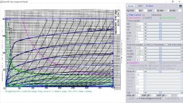
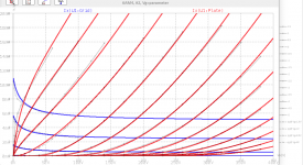
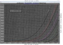
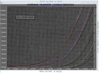
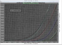
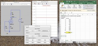
The transfer curve looks very normal in Adrian's model, esp. when add 50V to plate supply making it more close to original curve. Paint tool (right) can not model as good at upper extreme.
Attachments
Last edited:
I'm not taking sides here. I'm just trying to approach this the way I think an engineer should. If you have two descriptions of the same device that don't agree with each other, then build a test circuit to see which (if either!) is correct.BTW why do you think that everyone -who built equipments with this tube- has been wrong for the last seventy years and ruined a simple voltage measurement?
Adrian indicated that he will try to do that testing. It will be interesting to see what those test results are.
Gents,
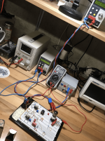
my 10 samples of the 6AM4 have been running now in a circuit as euro21 has in mind: Rk=100R, Ra=39k, Vsupp=582Vdc. For Rg, I took approximately half of the potentiometer, which is 47k (but that has nearly no influence, as the grid current is in nA range at -1V for this tube).
Result & comparison:
the average plate current of the 10 tubes is 9.34mA.
My model delivers 9.1mA
euro21 would expect 10mA
One has to say that I used a transformer which delivers 6.3Vac at 2.9A load, so the tube was a bit overheated. Hence the gm was a bit increased. I assume that the average plate current would be even closer to the Sim result when the heater would run at 6.3V exactly.
Conclusion:
My model reflects the average behavior of my 10 measured 6AM4 tubes quite well. There is no valid reason to complain.
One may say that another batch of this tube may behave quite different, and therefore one prefers a model according the datasheet. Well, everybody has the freedom to decide that for its own. I personally prefer to generate spice models based on a burntin golden sample out of a small batch, as such a model offers a much more precise grid current, which is of importance for example for overdriven guitar stages.
BR Adrian
Attachments
- Home
- Amplifiers
- Tubes / Valves
- Vacuum Tube SPICE Models