Regard to "WARNING: Less than two connections to node NC_01." in spice log this said it found floating points. Ground the unused tap 16 and 4 ohms with 100k or so makes the error disappeared.
Yes I know, the floating points cause the warning, not a big deal.
I ran your file and it runs fine. So why isn't my file running correctly? Still can't find anything wrong with my schematic or directives.
I ran your file and it runs fine. So why isn't my file running correctly? Still can't find anything wrong with my schematic or directives.
I told you already mine work with .tran 2m. I also don't get any result probably your .tran is to tight and cpu intensive, you try to relax .tran to see you can get any result.
No, V7 is correct. The 180 in the specifier is the phase. V3 phase is zero.
I finally got it to work, kind of, by re-entering the schematic and directives from scratch. Still runs an order of magnitude slower than the pentode version. I guess the UL is more computation-intensive.
It also gives UL distortion about 3 times the pentode diistortion, which I know empirically to be wrong. But that may be a matter of model accuracy rather than a SPICE issue.
I'm using the Ayumi, it's the only one I have. For this particular circuit in pentode configuration, it works well. It correlates pretty well with emprical results I got from the an actual cicuit. Maybe a tad optimistic. For anything else, I don't have real world data to check against.
It just seemed a bit unusual that the UL configuration would give 3 times the distortion vs pentode. 2.3% vs 0.7% @50W for the power stage. I don't expect distortion to be accurate, but as a rough number I didn't expect UL distortion to be greater than pentode, let alone a lot greater.
It just seemed a bit unusual that the UL configuration would give 3 times the distortion vs pentode. 2.3% vs 0.7% @50W for the power stage. I don't expect distortion to be accurate, but as a rough number I didn't expect UL distortion to be greater than pentode, let alone a lot greater.
Interesting revelation. I had followed Koonw's advice and put 100k resistors from unused secondaries to ground, just to get rid of the warnings. Now on a hunch I removed those resistors and the warnings came back. But also.... distortion went down from 2.3% to 1.9%, no other changes. Hmmm... I don't think that would happen in the real world.
Added a 1G resistance from 16 ohm tap to ground to make the "floating node" error go away in LTspice. Never really thought much about adding it as Micro-Cap has an option to add a 1G resistance to ground at all nodes. I forgot LTspice doesn't. Re-uploaded the library file ultpp16.txt below.
Code:
* =========================================================
.SUBCKT Ham1650N P1 Sg1 B Sg2 P2 O16 O8 O4 Com
* 60W Push Pull transformer, with Ultralinear taps at 40%
* 4300 to 16 ohms, 3db 15 to 60000 hz
* speaker taps at 8 and 4 ohms
* Hammond 1650N
*
* model generated by TransformerModels.xls 2012 Mar 31
*
LP1 1 Sg1 2.09554658287013
LS1 2 B 0.93135403683117
LS2 3 Sg2 0.93135403683117
LP2 4 P2 2.09554658287013
LA1 O8 5 0.00741645776380232
LA2 O4 6 0.00370822888190116
LA3 Com 7 0.02161314180004
KALL LP1 LS1 LS2 LP2 LA1 LA2 LA3 0.998434750532354
RP1 P1 1 30
RP2 Sg1 2 15
RP3 B 3 15
RP4 Sg2 4 30
RS1 O16 5 0.1
RS2 O8 6 0.1
RS3 O4 7 0.1
R16 O16 0 1G ; to avoid floating node
.ENDS Ham1650N
Attachments
Refer to post Vacuum Tube SPICE Models
The problem can be solved by any one of the followings depending on the errors in Spice.log, in this case used this option since Spice does find a operating points and but giving false results. Hope this helps.
.options GminSteps=0
.OP -- Find the DC operating point
Perform a DC operating point solution with capacitances open circuited and inductances short circuited. Usually a DC solution is performed as part of another analysis in order to find the operating point of the circuit. Use .op if you wish only this operating point to be found. The results will appear in a dialog box. After a .OP simulation, when you point at a node or current the .OP solution will appear on the status bar.
There is no guarantee that the operating point of a general nonlinear circuit can be found with successive linear approximations as is done in Newton-Raphson iteration. Should direct Newton iteration fail, LTspice tries a number of other methods to find an operating point. Below is a table of the methods used and the options settings required to disable a particular method.
Method
Directive to disable
Direct Newton Iteration
.options NoOpIterAdaptive Gmin Stepping
.options GminSteps=0Adaptive Source Stepping
.options SrcSteps=0Pseudo Transient
.options pTranTau=0Attachments
Last edited:
6U8A
I have searched this thread but was not able to find a library with the LT Spice models for the 6U8A triode and pentode sections.
Could someone please point me in the right direction? Thanks!
I have searched this thread but was not able to find a library with the LT Spice models for the 6U8A triode and pentode sections.
Could someone please point me in the right direction? Thanks!
TubeCad blog article exctract from John Broskie about triodes in the Spice simulation
source link Tube CAD Journal
source link Tube CAD Journal
Attachments
6u8a is glass version? You can use these models http://tubes.tubeampdesign.com/other/docs/Koren_Tubes.cir has better accuracy then one found in the Ayumi zip. The tube model name is either 6u8t or 6u8p. Other name is ecf82t and ecf82p. If not satisfied let us know, I can include grid current modelI have searched this thread but was not able to find a library with the LT Spice models for the 6U8A triode and pentode sections.
Could someone please point me in the right direction? Thanks!
Attachments
Last edited:
I have searched this thread but was not able to find a library with the LT Spice models for the 6U8A triode and pentode sections.
Could someone please point me in the right direction? Thanks!
Here are the Ayumi models.
Triode Section:
Code:
*
* Generic triode model: 6U8T
* Copyright 2003--2008 by Ayumi Nakabayashi, All rights reserved.
* Version 3.10, Generated on Sat Mar  8 22:41:00 2008
*            Plate
*            | Grid
*            | | Cathode
*            | | |
.SUBCKT 6U8T A G K
BGG   GG   0 V=V(G,K)+0.99995916
BM1   M1   0 V=(0.035181787*(URAMP(V(A,K))+1e-10))**-2.5690962
BM2   M2   0 V=(0.36863223*(URAMP(V(GG)+URAMP(V(A,K))/17.94587)+1e-10))**4.0690962
BP    P    0 V=0.0033085897*(URAMP(V(GG)+URAMP(V(A,K))/48.682314)+1e-10)**1.5
BIK   IK   0 V=U(V(GG))*V(P)+(1-U(V(GG)))*0.013182953*V(M1)*V(M2)
BIG   IG   0 V=0.0016542949*URAMP(V(G,K))**1.5*(URAMP(V(G,K))/(URAMP(V(A,K))+URAMP(V(G,K)))*1.2+0.4)
BIAK  A    K I=URAMP(V(IK,IG)-URAMP(V(IK,IG)-(0.0017567609*URAMP(V(A,K))**1.5)))+1e-10*V(A,K)
BIGK  G    K I=V(IG)
* CAPS
CGA   G    A 1.8p
CGK   G    K 2.8p
CAK   A    K 2p
.ENDS
Code:
*
* Generic pentode model: 6U8P
* Copyright 2003--2008 by Ayumi Nakabayashi, All rights reserved.
* Version 3.10, Generated on Sat Mar  8 22:41:03 2008
*            Plate
*            | Screen Grid
*            | |  Control Grid
*            | |  |  Cathode
*            | |  |  |
.SUBCKT 6U8P A G2 G1 K
BGG   GG   0 V=V(G1,K)+0.65071871
BM1   M1   0 V=(0.046006989*(URAMP(V(G2,K))+1e-10))**-2.7651713
BM2   M2   0 V=(0.35168575*(URAMP(V(GG)+URAMP(V(G2,K))/14.091647)))**4.2651713
BP    P    0 V=0.003445744*(URAMP(V(GG)+URAMP(V(G2,K))/40.068859))**1.5
BIK   IK   0 V=U(V(GG))*V(P)+(1-U(V(GG)))*0.018698107*V(M1)*V(M2)
BIG   IG   0 V=0.001722872*URAMP(V(G1,K))**1.5*(URAMP(V(G1,K))/(URAMP(V(A,K))+URAMP(V(G1,K)))*1.2+0.4)
BIK2  IK2  0 V=V(IK,IG)*(1-0.4*(EXP(-URAMP(V(A,K))/URAMP(V(G2,K))*15)-EXP(-15)))
BIG2T IG2T 0 V=V(IK2)*(0.74580496*(1-URAMP(V(A,K))/(URAMP(V(A,K))+10))**1.5+0.25419504)
BIK3  IK3  0 V=V(IK2)*(URAMP(V(A,K))+6302.5)/(URAMP(V(G2,K))+6302.5)
BIK4  IK4  0 V=V(IK3)-URAMP(V(IK3)-(0.0018526668*(URAMP(V(A,K))+URAMP(URAMP(V(G2,K))-URAMP(V(A,K))))**1.5))
BIP   IP   0 V=URAMP(V(IK4,IG2T)-URAMP(V(IK4,IG2T)-(0.0018526668*URAMP(V(A,K))**1.5)))
BIAK  A    K I=V(IP)+1e-10*V(A,K)
BIG2  G2   K I=URAMP(V(IK4,IP))
BIGK  G1   K I=V(IG)
* CAPS
CGA   G1  A  0.007p
CGK   G1  K  3p
C12   G1  G2 2p
CAK   A   K  3.5p
.ENDS
Code:
*
* Generic triode model: 6U8PT
* Copyright 2003--2008 by Ayumi Nakabayashi, All rights reserved.
* Version 3.10, Generated on Sat Mar  8 22:41:03 2008
*             Plate
*             | Grid
*             | | Cathode
*             | | |
.SUBCKT 6U8PT A G K
BGG   GG   0 V=V(G,K)+0.65071871
BM1   M1   0 V=(0.046006989*(URAMP(V(A,K))+1e-10))**-2.7651713
BM2   M2   0 V=(0.35168575*(URAMP(V(GG)+URAMP(V(A,K))/14.091647)+1e-10))**4.2651713
BP    P    0 V=0.003445744*(URAMP(V(GG)+URAMP(V(A,K))/40.068859)+1e-10)**1.5
BIK   IK   0 V=U(V(GG))*V(P)+(1-U(V(GG)))*0.018698107*V(M1)*V(M2)
BIG   IG   0 V=0.001722872*URAMP(V(G,K))**1.5*(URAMP(V(G,K))/(URAMP(V(A,K))+URAMP(V(G,K)))*1.2+0.4)
BIAK  A    K I=URAMP(V(IK,IG)-URAMP(V(IK,IG)-(0.0018526668*URAMP(V(A,K))**1.5)))+1e-10*V(A,K)
BIGK  G    K I=V(IG)
* CAPS
CGA   G    A 2p
CGK   G    K 3p
CAK   A    K 3.5p
.ENDSTubeCad blog article exctract from John Broskie about triodes in the Spice simulation
source link Tube CAD Journal
It is very important to know that there isn't just one triode spice model approach, like the article fragment may let suppose.
Instead, there are dozens of very different triode model approaches, all with different strenghs and drawbacks.
If one wish to get an overview over this topic, here is my essay I published in 2018. It took me about 2 years to analyse the most important approaches I have found in my web research, and finally merged the best ideas to a new model.
http://adrianimmler.simplesite.com/440956786
all the best, Adrian
Attachments
Last edited:
 Thanks for sharing
EF54 model - Pentode
Hi,
I am looking for pentode model of EF54.
datasheet: https://tubedata.altanatubes.com.br/sheets/154/e/EF54.pdf
Hi,
I am looking for pentode model of EF54.
datasheet: https://tubedata.altanatubes.com.br/sheets/154/e/EF54.pdf
Try this:
Code:
* Created on 07/20/2020 20:43 using paint_kip.jar
* [URL="http://www.dmitrynizh.com/tubeparams_image.htm"]www.dmitrynizh.com/tubeparams_image.htm[/URL]
* Plate Curves image file: ef54.png
* Data source link: <plate curves URL>
*----------------------------------------------------------------------------------
.SUBCKT EF54 P G2 G K ; LTSpice tetrode.asy pinout
* .SUBCKT EF54 P G K G2 ; Koren Pentode Pspice pinout
+ PARAMS: MU=85.26 KG1=650.63 KP=300.28 KVB=10.8 VCT=0.2 EX=1.4 KG2=6078.24 KNEE=93.71 KVC=1.696
+ KLAM=1.242E-8 KLAMG=3.213E-4 KD=1.15E-4 KC=3.067 KR1=4.508E-6 KR2=1.739 KVBG=-0.004766 KB1=2.705 KB2=4.113 KB3=2.171 KB4=2.792 KVBGI=0.2282 KNK=-0.2271 KNG=0.005063 KNPL=54 KNSL=12.21 KNPR=128.4 KNSR=33.06
+ CCG=6.2P CGP=0.02P CCP=4.9P VGOFF=-0.6 IGA=0.001 IGB=0.3 IGC=8 IGEX=1.88
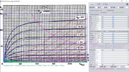
* Vp_MAX=300 Ip_MAX=30 Vg_step=0.5 Vg_start=0 Vg_count=10
* X_MIN=34 Y_MIN=113 X_SIZE=830 Y_SIZE=487 FSZ_X=1296 FSZ_Y=736 XYGrid=false
* Rp=1400 Vg_ac=20 P_max=3 Vg_qui=-2.25 Vp_qui=300
* showLoadLine=n showIp=y isDHP=n isPP=n isAsymPP=n isUL=n showDissipLimit=y
* showIg1=y isInputSnapped=y addLocalNFB=n
* XYProjections=n harmonicPlot=y dissipPlot=n
* UL=0.43 EG2=250 gridLevel2=y addKink=y isTanhKnee=n advSigmoid=y
*----------------------------------------------------------------------------------
RE1 7 0 1G ; DUMMY SO NODE 7 HAS 2 CONNECTIONS
E1 7 0 VALUE= ; E1 BREAKS UP LONG EQUATION FOR G1.
+{V(G2,K)/KP*LOG(1+EXP((1/MU+(VCT+V(G,K))/SQRT(KVB+V(G2,K)*V(G2,K)))*KP))}
RE2 6 0 1G ; DUMMY SO NODE 6 HAS 2 CONNECTIONS
E2 6 0 VALUE={(PWR(V(7),EX)+PWRS(V(7),EX))} ; Kg1 times KIT current
E4 8 0 VALUE={V(P,K)/KNEE/(KVBGI+V(6)*KVBG)}
E5 81 0 VALUE={PWR(V(8),KB1)}
E6 82 0 VALUE={PWR(V(8),KB2)}
E7 83 0 VALUE={PWR(V(8),KB3)}
E8 9 0 VALUE={PWR(1-EXP(-V(81)*(KC+KR1*V(82))/(KD+KR2*V(83))),KB4)*1.5708}
RE4 8 0 1
RE5 81 0 1
RE6 82 0 1
RE7 83 0 1
RE8 9 0 1
RE21 21 0 1
E21 21 0 VALUE={V(6)/KG1*V(9)} ; Ip with knee but no slope and no kink
RE22 22 0 1 ; E22: kink curr deviation for plate
E22 22 0 VALUE={V(21)*LIMIT(KNK-V(G,K)*KNG,0,0.3)*(-ATAN((V(P,K)-KNPL)/KNSL)+ATAN((V(P,K)-KNPR)/KNSR))}
G1 P K VALUE={V(21)*(1+KLAMG*V(P,K))+KLAM*V(P,K) + V(22)}
G2 G2 K VALUE={V(6)/KG2*(KVC-V(9))/(1+KLAMG*V(P,K)) - V(22)}
RCP P K 1G ; FOR CONVERGENCE
C1 K G {CCG} ; CATHODE-GRID 1
C2 G P {CGP} ; GRID 1-PLATE
C3 K P {CCP} ; CATHODE-PLATE
RE23 G 0 1G
GG G K VALUE={(IGA+IGB/(IGC+V(P,K)))*(MU/KG1)*
+(PWR(V(G,K)-VGOFF,IGEX)+PWRS(V(G,K)-VGOFF,IGEX))}
.ENDS
*$Attachments
Last edited:
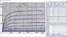
The horizontal axis of the image size is a bit off, it's corrected now:
Code:
**** EF54 ******************************************
* Created on 07/21/2020 03:32 using paint_kip.jar
* [URL="http://www.dmitrynizh.com/tubeparams_image.htm"]Model Paint Tools: Trace Tube Parameters over Plate Curves, Interactively[/URL]
* Plate Curves image file: ef54.png
* Data source link: <plate curves URL>
*----------------------------------------------------------------------------------
.SUBCKT EF54 P G2 G K ; LTSpice tetrode.asy pinout
* .SUBCKT EF54 P G K G2 ; Koren Pentode Pspice pinout
+ PARAMS: MU=80 KG1=636.9 KP=593.25 KVB=11.56 VCT=0.1359 EX=1.33 KG2=6078.24 KNEE=80.59 KVC=1.696
+ KLAM=7.546E-9 KLAMG=2.978E-4  KD=-1.251E-5 KC=2.975 KR1=-8.301E-5 KR2=3.095 KVBG=-4.431E-5 KB1=3.598 KB2=1.316 KB3=2.974 KB4=2.066 KVBGI=0.1073 KNK=-0.2271 KNG=0.005063 KNPL=54 KNSL=12.21 KNPR=128.4 KNSR=33.06
+ CCG=6.2P CGP=0.02P CCP=4.9P VGOFF=-0.6 IGA=0.001 IGB=0.3 IGC=8 IGEX=1.88
* Vp_MAX=300 Ip_MAX=30 Vg_step=0.5 Vg_start=0 Vg_count=10
* X_MIN=38 Y_MIN=106 X_SIZE=819 Y_SIZE=489 FSZ_X=1289 FSZ_Y=729 XYGrid=false
* Rp=1400 Vg_ac=20 P_max=3 Vg_qui=-2.25 Vp_qui=300
* showLoadLine=n showIp=y isDHP=n isPP=n isAsymPP=n isUL=n showDissipLimit=y
* showIg1=y isInputSnapped=y addLocalNFB=n
* XYProjections=n harmonicPlot=y dissipPlot=n
* UL=0.43 EG2=250 gridLevel2=y addKink=y isTanhKnee=n advSigmoid=y
*----------------------------------------------------------------------------------
RE1  7 0  1G    ; DUMMY SO NODE 7 HAS 2 CONNECTIONS
E1   7 0  VALUE=  ; E1 BREAKS UP LONG EQUATION FOR G1.
+{V(G2,K)/KP*LOG(1+EXP((1/MU+(VCT+V(G,K))/SQRT(KVB+V(G2,K)*V(G2,K)))*KP))}
RE2  6 0  1G    ; DUMMY SO NODE 6 HAS 2 CONNECTIONS
E2  6 0  VALUE={(PWR(V(7),EX)+PWRS(V(7),EX))} ; Kg1 times KIT current
E4   8 0  VALUE={V(P,K)/KNEE/(KVBGI+V(6)*KVBG)}
E5  81 0  VALUE={PWR(V(8),KB1)}
E6  82 0  VALUE={PWR(V(8),KB2)}
E7  83 0  VALUE={PWR(V(8),KB3)}
E8   9 0  VALUE={PWR(1-EXP(-V(81)*(KC+KR1*V(82))/(KD+KR2*V(83))),KB4)*1.5708}
RE4  8 0  1
RE5 81 0  1
RE6 82 0  1
RE7 83 0  1
RE8  9 0  1
RE21 21 0 1
E21  21 0 VALUE={V(6)/KG1*V(9)} ; Ip with knee but no slope and no kink
RE22 22 0 1 ; E22: kink curr deviation for plate
E22  22 0 VALUE={V(21)*LIMIT(KNK-V(G,K)*KNG,0,0.3)*(-ATAN((V(P,K)-KNPL)/KNSL)+ATAN((V(P,K)-KNPR)/KNSR))}
G1   P K  VALUE={V(21)*(1+KLAMG*V(P,K))+KLAM*V(P,K) + V(22)}
G2   G2 K  VALUE={V(6)/KG2*(KVC-V(9))/(1+KLAMG*V(P,K)) - V(22)}
RCP  P K  1G     ; FOR CONVERGENCE
C1   K G  {CCG}  ; CATHODE-GRID 1
C2   G P  {CGP}  ; GRID 1-PLATE
C3   K P  {CCP}  ; CATHODE-PLATE
RE23 G 0 1G
GG G K VALUE={(IGA+IGB/(IGC+V(P,K)))*(MU/KG1)*
+(PWR(V(G,K)-VGOFF,IGEX)+PWRS(V(G,K)-VGOFF,IGEX))}
.ENDS
*$
Attachments
Last edited:
- Home
- Amplifiers
- Tubes / Valves
- Vacuum Tube SPICE Models