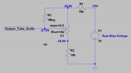
A bias tap of 50 volts AC is going to give you a rectified bias voltage of about -70 volts. You will need a voltage divider to drop that voltage by about 2/3. You want this to be adjustable but generally don't need the entire range (about 70 volts in this case). Usually the range needs to be only about 5 or 10 volts either side of the nominal bias voltage, which I have taken to be about -27 volts.
Here is a circuit that should do what you want. if you want to narrow the range, just increase both R1 and R2.
R3 is a "safety" resistor. If the wiper on the potentiometer were to lift, R3 will make the bias voltage more negative (about -37 volts in this circuit), reducing output tube idle current. Without this resistor, an open wiper will cause the output tubes to lose bias altogether, making them conduct heavily. This condition will almost certainly destroy the tubes but it can also damage the output and power transformers.
I hope this helps.
Attachments
Thank you Ray, I will give that a try.
I do intend to install a bias pot in the actual amp I'm building. I thought I would try and get the circuit working with fixed resistors first.
Thanks,
David
I do intend to install a bias pot in the actual amp I'm building. I thought I would try and get the circuit working with fixed resistors first.
Thanks,
David
If you want to work with fixed resistors first, just replace the 10k potentiometer with two 4.7k resistors in series and take the bias voltage from the junction of these two resistors. That should at least give you something to play with.
Here's a dropdown for selecting output xfrmrs. Place "ultpp16.txt" and "ultpp.txt files in your ...\lib\sub folder, depending on where you have your lib folder located, for instance in \Documents and Settings for LTspiceXVII. Do not place these files in the LTspiceXVII program folder. I have LTspiceIV running under WINE in Linux, that's why in it appears to be in the program folder.Do we have models and symbols for some of the more popular Hammond or Edcor output transformers? I couldn't find with search. Any pointers much appreciated.
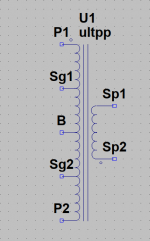
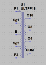
Place "ultpp16_dd.asy" and "ultpp_dd.asy" files in your ...\lib\sym folder as explained above. I've uploaded the the symbol (asy) named as "".asy.txt, so you will have to drop the ".txt" from the filename. I have mine under ...\lib\sym\misc. You could create a directory (folder) under ...\lib\sym\... by any name you wish.
Now that you've done the above, place the dropdown symbol of your choice (screenshots below) on your schematic. Right click on the SYMBOL, not the text. A dialog box will appear. Right click or double left click on the "SpiceModel" line under "value". A dropbox will appear, as shown below. Left click the dropdown arrow to choose your transformer model and voila.
That's all I have at the moment, but here are two links concerning a spreadsheet posted by forum member Robert McLean.
SPICE Transformer Model Spreadsheet
spice model for UL output transformer?
All the best.
Attachments

Last edited:
Hello, I'm trying to model a negative bias voltage supply circuit in LTSpice.
Nothing I try works.
To add to what Ray said:
The reason it doesn't work is the schematic. You have a DC positive voltage source V1 feeding into a reverse-biased diode, so nothing comes out.
If 50V is the raw secondary of your transformer, you need to represent it as an AC source of the correct amplitude and frequency.
Crazy me forgot to rename the asy files. Hey, it sucks to get old. 😛
Hi, are there any models available for edcor single ended output transformers or do you need to use Rob McLeans spreadsheet to develop your own?
Edit: I have the spice directives from McLean's spreadsheet, I meant to say the nice single ended symbol. Tried to draw it in the symbol editor with arcs for the inductor shape but couldn't get it neat enough.Hi, are there any models available for edcor single ended output transformers or do you need to use Rob McLeans spreadsheet to develop your own?
Here's a dropdown for selecting output xfrmrs. Place "ultpp16.txt" and "ultpp.txt files in your ...\lib\sub folder...
I got it working, was easy.
Your OPT symbol with dropdown pick list works great, and looks really good in the schematic too.
Thanks very much for this.
--
Edit: I have the spice directives from McLean's spreadsheet, I meant to say the nice single ended symbol. Tried to draw it in the symbol editor with arcs for the inductor shape but couldn't get it neat enough.
Here are the symbols for Robert McLean's transformer models.
SPICE Transformer Model Spreadsheet
You may want to make other models based on the above which is standard Zener diode model. There could other ways.
Thanks Koonw. How did you determine series resistance RS?
Also, I see you use bv and nbv as the breakdown and regulating voltage. Does that work in a model that's a Zener? I mean, will it really behave like a tube, i.e. will it only conduct once it goes over bv but then regulate at nbv?
Also, I see you use bv and nbv as the breakdown and regulating voltage. Does that work in a model that's a Zener? I mean, will it really behave like a tube, i.e. will it only conduct once it goes over bv but then regulate at nbv?
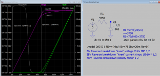
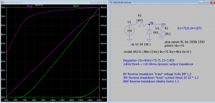
Yes should good enough as break down in Zener is what gas ion does in voltage regulator tube, then to act as regulator only needs 3 parameters:
BV Reverse breakdown "knee" voltage Volts
IBV Reverse breakdown "knee" current Amps
NBV Reverse breakdown ideality factor
Have found this IEEE article Gas Discharge Tube Modeling With PSpice
BV Reverse breakdown "knee" voltage Volts
IBV Reverse breakdown "knee" current Amps
NBV Reverse breakdown ideality factor
Have found this IEEE article Gas Discharge Tube Modeling With PSpice
Attachments
Last edited:
The model of a gas tube regulator is quite complex (certainly more complex than a Zener).
1. Do not start with the firing voltage, and forget about the voltage when the regulator goes dark again (somewhere below its operating voltage).
Instead:
2. Work on how well it regulates as intended:
Example: OD3:
Min operating current 5mA
Max operating current 40mA
Operating Voltage, 150V
Delta voltage from 4mA to 40mA draw: 4V
4V/35mA = 114.3 Ohms dynamic impedance
3. Now, the finishing factors: you need at least 185V B+ at the top of the series dropping resistor that supplies the Anode voltage.
Ionization voltage is 160V.
That means there is at least 25V across the series resistor from B+ to the Anode when the tube ionizes.
Those are a complete set of factors. Build a model based on the above.
Then pick a different regulator tube type, and fill in the new numbers accordingly.
If you have large amounts of capacitive and/or inductive reactance in the gas tube regulator circuit, you are on your own.
Many a great oscillator has been created.
I do not use Spice, I do not like software (neither does my brain).
Nothing personal, I just relate to the world differently.
Last edited:
Thank you for your in time advice, four calculating output Z without a model by just refer to datasheet. But I need to verify the correctness of model in case someone wants to use it. I now have verified the regulation of 0A3 is 3.85v(4v).
PS param NBV could be adjusted up by 10 points if necessary.
PS param NBV could be adjusted up by 10 points if necessary.
Attachments
Last edited:
I too shied away from using software to develop my projects for many years. I had been aware of LTSpice for a long time, because it was continually referred to by other diyAudio members when I was searching a topic. Then came my problems with trying to squeeze enough drive from the 6SN7 for the 300B in single-ended operation. You were instrumental in persuading me to put a IXCP10M90S as the plate load, which solved the problem very nicely (100V and more peak drive). I was so eager to test various HT voltages and grid bias settings, that I decided after many years to bite the bullet and learn how to use LTSpice. Earlier this year, Administrator Mooly guided me through it with patience and understanding. He has written a comprehensive tutorial on it. He had me up and running in less than a week, starting with simple DC simulations, right through to doing a Fast Fourier Transform and distortion calculations on my tube amp circuits, and now I'm flying solo. It's the most rewarding bit of study I have ever done, and using the application has expanded my horizons enormously.I do not use Spice, I do not like software (neither does my brain).
Nothing personal, I just relate to the world differently.
Just a few thoughts. Like you say, people relate to the world differently.
- Home
- Amplifiers
- Tubes / Valves
- Vacuum Tube SPICE Models