Revised Ayumi GU50 Pentode Model
Fresh from the oven, get it while it's hot...😛
Fresh from the oven, get it while it's hot...😛
Code:
*
*
* Generic pentode model: GU50_AN
* Copyright 2003--2008 by Ayumi Nakabayashi, All rights reserved.
* Version 3.10, Generated on Thu Dec 23 17:30:30 2014
*               Plate
*               | Screen Grid
*               | |  Control Grid
*               | |  |  Cathode
*               | |  |  |
.SUBCKT GU50_AN A G2 G1 K
BGG   GG   0 V=V(G1,K)+1
BM1   M1   0 V=(0.10436355*(URAMP(V(G2,K))+1e-10))**-0.94152046
BM2   M2   0 V=(0.61437126*(URAMP(V(GG)+URAMP(V(G2,K))/3.6950521)))**2.4415205
BP    P    0 V=0.0013346082*(URAMP(V(GG)+URAMP(V(G2,K))/6.0143635))**1.5
BIK   IK   0 V=U(V(GG))*V(P)+(1-U(V(GG)))*0.00086083603*V(M1)*V(M2)
BIG   IG   0 V=0.000667**408*URAMP(V(G1,K))**1.5*(URAMP(V(G1,K))/(URAMP(V(A,K))+URAMP(V(G1,K)))*1.2+0.4)
BIK2  IK2  0 V=V(IK,IG)*(1-0.4*(EXP(-URAMP(V(A,K))/URAMP(V(G2,K))*15)-EXP(-15)))
BIG2T IG2T 0 V=V(IK2)*(0.952380952*(1-URAMP(V(A,K))/(URAMP(V(A,K))+10))**1.5+0.047619048)
BIK3  IK3  0 V=V(IK2)*(URAMP(V(A,K))+11100)/(URAMP(V(G2,K))+11100)
BIK4  IK4  0 V=V(IK3)-URAMP(V(IK3)-(0.0010136338*(URAMP(V(A,K))+URAMP(URAMP(V(G2,K))-URAMP(V(A,K))))**1.5))
BIP   IP   0 V=URAMP(V(IK4,IG2T)-URAMP(V(IK4,IG2T)-(0.0010136338*URAMP(V(A,K))**1.5)))
BIAK  A    K I=V(IP)+1e-10*V(A,K)
BIG2  G2   K I=URAMP(V(IK4,IP))
BIGK  G1   K I=V(IG)
* CAPS
CGA   G1  A  0.1p
CGK   G1  K  8.4p
C12   G1  G2 5.6p
CAK   A   K  9.2p
.ENDSHmm. In Ayumi library which I have, there is a pure triode model. Works perfectly with triode sym:
* Generic triode model: 6GW8PT
* Copyright 2003--2008 by Ayumi Nakabayashi, All rights reserved.
* Version 3.10, Generated on Sat Mar 8 22:40:12 2008
* Plate
* | Grid
* | | Cathode
* | | |
.SUBCKT 6GW8PT A G K
BGG GG 0 V=V(G,K)+0.84112562
BM1 M1 0 V=(0.01029284*(URAMP(V(A,K))+1e-10))**-0.37211195
BM2 M2 0 V=(0.80123414*(URAMP(V(GG)+URAMP(V(A,K))/19.311081)+1e-10))**1.872112
BP P 0 V=0.0043151181*(URAMP(V(GG)+URAMP(V(A,K))/24.10167)+1e-10)**1.5
BIK IK 0 V=U(V(GG))*V(P)+(1-U(V(GG)))*0.0025686773*V(M1)*V(M2)
BIG IG 0 V=0.0021575591*URAMP(V(G,K))**1.5*(URAMP(V(G,K))/(URAMP(V(A,K))+URAMP(V(G,K)))*1.2+0.4)
BIAK A K I=URAMP(V(IK,IG)-URAMP(V(IK,IG)-(0.002428883*URAMP(V(A,K))**1.5)))+1e-10*V(A,K)
BIGK G K I=V(IG)
* CAPS
CGA G A 4.2p
CGK G K 5.8p
CAK A K 7.6p
.ENDS
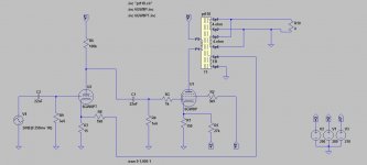
This model is the pentode as triode
see my sim
Attachments

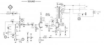
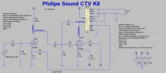
I tried the triode model provided by jazbo8 however the anode voltage is very low phlilips has it on 120 volt is this a mistake in the philips drawing or is the model not oke
Attachments
I tried the triode model provided by jazbo8 however the anode voltage is very low phlilips has it on 120 volt is this a mistake in the philips drawing or is the model not oke
I think you are confusing the triode section of this tube with the pentode section strapped for triode operation. The two are not the same, and I think you are trying to use the triode strapped pentode model where you should be using the triode section model.
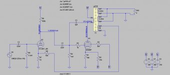
Try the attached triode section model: file 6GW8T.txt (rename to 6GW8T.inc), and match the name of the first triode (6GW8T). When I run the simulation, I get about 70.5 volts at the plate of the first triode.
Ray
Attachments
Yes i got the same with the model from jazbo8
But philips says in the drawing that the plate is about 120 Volts
But philips says in the drawing that the plate is about 120 Volts
I simulated a set of plate curves for this model and they compare quite well to the published curves for the triode section of this tube (see attached data sheet).
Plotting a manual load line also shows close agreement with the simulated results. I believe the problem is the cathode resistor R7. Are you sure this is supposed to be 15 ohms? That small value provides very little (negative) bias for the tube (only about 20 mV). A cathode resistor of 1.5k produces a much more normal operating point for this tube. With R7 = 1.5k, the tube operates with 117.8 volts on the plate at 920 uA, with a (negative) grid bias of 760 mV. With these values, I get a good clean output signal up to 4 volts peak (2 watts into 4 ohms). Of course, if you want more closed loop gain then you will also need to increase the value of feedback resistor R8.
Ray
Attachments
Last edited:
see pictures in post 663
Yes, I saw that. Just commenting that the triode section model looks like a good match to the published plate curves, and a manual paper load line will give results similar to the simulation with the components indicated. I can't explain how to get 120 volts at the plate with this circuit; maybe someone else can.
Good very wel be that philips made a mistake here i can't control this i don,t have the TV anymore
There is nothing wrong with Philip's schematic, except the B+ voltages are wrong, the +2, +3, +7 most likely refer to nodes on the power supply and not the actual voltages. In any case, the Ayumi triode section model for the ECL86 does not do a good job of modeling the reverse grid current, which is needed for the grid leak bias used in the Philips schematic, to do so, you need to get or build a model that does. So for this particular circuit, the Ayumi model should not be used.
My bad, missed the notations on the asc file... anyway, you need to find a triode model that has an accurate grid current code.the voltages i got indeed from the schematic
There is nothing wrong with Philip's schematic, except the B+ voltages are wrong, the +2, +3, +7 most likely refer to nodes on the power supply and not the actual voltages. In any case, the Ayumi triode section model for the ECL86 does not do a good job of modeling the reverse grid current, which is needed for the grid leak bias used in the Philips schematic, to do so, you need to get or build a model that does. So for this particular circuit, the Ayumi model should not be used.
Thanks for that insight. I guess I was stuck on the idea that the input stage was intended to work like a typical common cathode gain stage with cathode bias. This makes sense now, although I personally wouldn't approach the design that way.
I have used this:
.SUBCKT 6N2P-EV 1 2 3 ; P G C (Triode)
* Modified from 12AX7A data by Arto Salo; CGP is 1.0 pF reduced, other parameters unchanged
* Verified with LT-Spice simulations and actual circuit
X1 1 2 3 TRIODE MU=100.26 EX=1.394 KG1=1651.8 KP=17950.75 KVB=524.4 VCT=0.50 RGI=2000 CCG=2.3p CGP=1.4p CCP=0.9p ;
.ENDS 6N2P-EV
On that note there was missing something
Code:
.SUBCKT 6N2P-EV 1 2 3 ; P G C (Triode)
* Modified from 12AX7A data by Arto Salo; CGP is 1.0 pF reduced, other parameters unchanged
* Verified with LT-Spice simulations and actual circuit
X1 1 2 3 TRIODE MU=100.26 EX=1.394 KG1=1651.8 KP=17950.75 KVB=524.4 VCT=0.50 RGI=2000 CCG=2.3p CGP=1.4p CCP=0.9p ;
.ENDS 6N2P-EV
*
.SUBCKT TRIODE 1 2 3 ; A G C
E1  7 0 VALUE={V(1,3)/KP*LOG(1+EXP(KP*(1/MU+(V(2,3)+VCT)/SQRT(KVB+V(1,3)*V(1,3)))))}
RE1 7 0 1G
G1  1 3 VALUE={(PWR(V(7,0),EX)+PWRS(V(7,0),EX))/KG1}
RCP 1 3 1G    ; TO AVOID FLOATING NODES IN MU-FOLLOWER
C1  2 3 {CCG}  ; CATHODE-GRID
C2  2 1 {CGP}  ; GRID=PLATE
C3  1 3 {CCP}  ; CATHODE-PLATE
D3  5 3 DX     ; FOR GRID CURRENT
R1  2 5 {RGI}  ; FOR GRID CURRENT
.ENDS           TRIODE
*
.MODEL DX D(IS=1N RS=1 CJO=10PF TT=1N) ; diode used by the Triode, Pentode Beam Tetrode models
Last edited:
Here (attached) is the tube libray that should contain all that is needed to make 6N2P-EV model to work.
EDIT: I re-named it to tubelibrary.txt, because .inc files can not be attached.
EDIT: I re-named it to tubelibrary.txt, because .inc files can not be attached.
Attachments
Last edited:
Here (attached) is the tube libray that should contain all that is needed to make 6N2P-EV model to work.
EDIT: I re-named it to tubelibrary.txt, because .inc files can not be attached.
Thats why i always zip the files
And these are the same as the Norman Koran models
Last edited:
- Home
- Amplifiers
- Tubes / Valves
- Vacuum Tube SPICE Models