Hi Adrian,
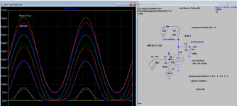
I changed VgOff from -2.5v to -0.8v, the Ig plot for this schematic for Vg 3v to -3v becomes almost identical to your updated model. Do you think we can use Paint Tool but how VgOff is determined, you know? There are lots of A2 models similar to Paint Tool, is it trial and error (like mine)?
4P1L model improved – Bartola(R) Valves
Attachments
Last edited:
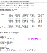
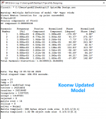
Some Comparisons.
I've run the two new models for the Raytheon 6SN7 using the same schematic, under the same conditions again, and here are the results:
I've run the two new models for the Raytheon 6SN7 using the same schematic, under the same conditions again, and here are the results:
Attachments
Hi Adrian,
I changed VgOff from -2.5v to -0.8v, the Ig plot for this schematic for Vg 3v to -3v becomes almost identical to your updated model. Do you think we can use Paint Tool but how VgOff is determined, you know? There are lots of A2 models similar to Paint Tool, is it trial and error (like mine)?
4P1L model improved – Bartola(R) Valves
Hi Koonw,
It seems that my grid contact voltage Vctg has the same function as VgOff has in the Paint Tool, so just set VgOff= -Vct. Best determination is already done with my excel-least-mean-square-approach, so I recommend to overtake VgOff=-0.513V.
What do you mean with A2 models?
What do you mean with A2 models? I think it meant DHT model in A2, no difference to indirect heated triode? In Paint tool I saw DHT model is an option for modeling but only with A1, since A2 involved grid current and those curves must be traced by e.g uTracer. The grid model equation is same. |VgOff ranged from 3v to -3v found in those models. Thank you so VgOff same as -VCT is manually determined in software application. So you could have good curve trace with more than one particular VgOff (-VCT), then adjust it to match the original curve, and that become the final value. Is it portable so it can be used in other models?
Koonw, did you notice that there is a significant difference in the THD between the updated model and the previous one you generated, after I performed the latest simulations?I've run the two new models for the Raytheon 6SN7 using the same schematic, under the same conditions again, and here are the results:
Last edited:
Koonw, did you notice that there is a significant difference in the THD between the updated model and the previous one you generated, after I performed the latest simulations?
I noticed it, I got the same result as you. The zero grid curve is better match than the older one, a bit not much, so could explain the difference. You can also try the value of VgOff in the model change -2.5V to -0.8 see any difference. See my post on this earlier.
ps: I just tested it, change -2.5V to -0.8 does not make any difference. So must be the little adjustment on zero bias curve.
Also if Va current is doubled, distortion is reduced, and if only use a single section distortion is also less, looks like current is divided, too little for full operation?? Or double section add complexity also..
Last edited:
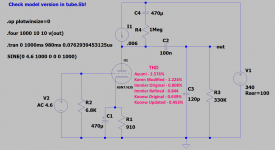
Here is a 6sn7 model that has "best" distortion among 7 models I sim. The reason is perhaps it does have not model grid current at all so it amplified cleanly without any interference.
Code:
.subckt 6sn7 P G K
Bp P K I=
+ (0.02003791851m)*uramp(V(P,K)*ln(1.0+(-0.07740549711)+exp((4.618036737)+
+ (4.618036737)*((20.85288965)+(-110.4389272m)*V(G,K))*V(G,K)/sqrt((28.13407639)**2+
+ (V(P,K)-(7.118597372))**2)))/(4.618036737))**(1.380047579)
Cgp G P 4.0pF
Cgk G K 2.6pF
Cpk P K 0.7pF
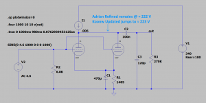
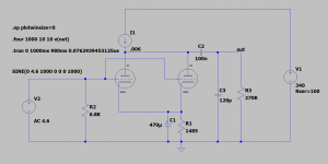
.ends 6sn7Because I'm using the IXCP10M90S CCS, which has a dynamic resistance of about 1Megohm (as calculated by another great graph interpreter on diyAudio), as a plate load, I have a very wide latitude to set the grid bias with Rk, anywhere between -5V to -10 Volts, before I hit appreciable grid current on one side, or come up against the 340 Volt HT brick wall on the other. Any of these bias points enables an output of up to 90 Volts peak, which is more than sufficient to drive any 300B SET topology.Here is a 6sn7 model that has "best" distortion among 7 models I sim. The reason is perhaps it does have not model grid current at all so it amplified cleanly without any interference.
But setting Rk and therefore Grid bias has a very big impact on the THD. So, I suppose, using an average for simulation model results is the way forward. Setting it as high as possible, consistent with sufficient output (right up until my output waveform flattens), gives the best distortion figure in all models, but, of course, I want to achieve the lowest THD in the 6SN7 driver stage, in order to allow the 300B to shine through. So, I really must rely on one model. It's not going to be the Koren Modified. All the rest, show better THD figures, the higher I set Rk.
Maybe, on second thoughts, if they all give lower THD with increased RK, I need only to worry about the output voltage. which can vary quite a bit with each model. I really need to measure the maximum peak output voltage with the present bias point.
Attachments
Last edited:
Hi there, regard the above post: have you consider fixed (variable) grid bias? I just did a quick test and discover my model give even lower distortion at the same output level. Do monitor the grid current wave to be sure when comparing each model.
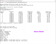
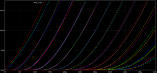
1 6sn7_ry
2 6sn7_rca
3 Adrian 6sn7
4 Ayumi
5 Curvecaptor
6 Koren
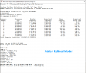
1 6sn7_ry
2 6sn7_rca
3 Adrian 6sn7
4 Ayumi
5 Curvecaptor
6 Koren
Attachments
Last edited:
Thanks for all that. There's a lot there to sink my teeth into. Cheers.Hi there, regard the above post: have you consider fixed (variable) grid bias? I just did a quick test and discover my model give even lower distortion at the same output level. Do monitor the grid current wave to be sure when comparing each model.
1 6sn7_ry
2 6sn7_rca
3 Adrian 6sn7
4 Ayumi
5 Curvecaptor
6 Koren
Hi guys.
Im looking for curves
Triode straped QB3/300 somone can help?
Hi Yasioo
See my QB3/300 model in my message # 2223 in this thread. It works also triode strapped.
all the best, Adrian
Hi Yasioo
See my QB3/300 model in my message # 2223 in this thread. It works also triode strapped.
all the best, Adrian
THANKS!
Yes, indeed. I'm going to use a 6J5 instead. Lots of them on the internet, but they are going up in price all the time. I might use a 6C2C Russian equivalent - freely available in Eastern Europe. The curves for the 6J5 look identical, so I presume a 6SN7 Spice model will give the same results.Also if Va current is doubled, distortion is reduced, and if only use a single section distortion is also less, looks like current is divided, too little for full operation?? Or double section add complexity also..
Last edited:
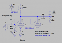
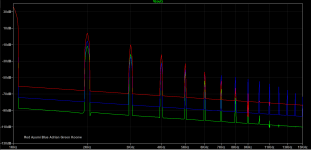
Updated schematic simulated for Total Harmonic Distortion with 6 different models.I noticed it, I got the same result as you. The zero grid curve is better match than the older one, a bit not much, so could explain the difference. You can also try the value of VgOff in the model change -2.5V to -0.8 see any difference. See my post on this earlier.
ps: I just tested it, change -2.5V to -0.8 does not make any difference. So must be the little adjustment on zero bias curve.
Also if Va current is doubled, distortion is reduced, and if only use a single section distortion is also less, looks like current is divided, too little for full operation?? Or double section add complexity also..
Attachments
Updated schematic simulated for Total Harmonic Distortion with 6 different models.
In use, I've also found that the Ayumi 6SN7 model yields far higher predicted THD than others. (I've been using a 6SN7 model Wayne made a while back from the GE datasheet.)
Is the Ayumi model that far off? Or is that the accurate one? Or... Are THD predictions in LTspice totally unreliable? I don't know.
Hard to say. The 2 Koonw ones and the 2 Immler ones were done very recently at my request. So, I'll shoot for an average of those 4.In use, I've also found that the Ayumi 6SN7 model yields far higher predicted THD than others. (I've been using a 6SN7 model Wayne made a while back from the GE datasheet.)
Is the Ayumi model that far off? Or is that the accurate one? Or... Are THD predictions in LTspice totally unreliable? I don't know.
When compared with original curve 6sn7 plot using Ayumi's shows that it's off in 2 areas , 0V and -24 at the extreme (by quite a margin), thus distortion set in, FFT reveals it. In general what I heard the complaint about Ayumi's is off a bit more towards the right extreme end.
Attachments
Ayumi's models are "a class of its own", because he claimed to use only 4 parameters (sometimes 6 parameters), and for that extreme low number of parameters, the achievable accuracy is quite impressive.
But it is logical, that another approach like mine or Dmtri's with more parameters have the potential for more accuracy.
But it is logical, that another approach like mine or Dmtri's with more parameters have the potential for more accuracy.
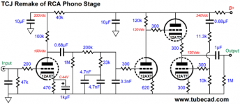
https://frank.pocnet.net/sheets/020/1/12AX7S.pdf
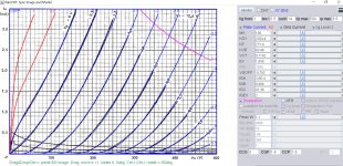
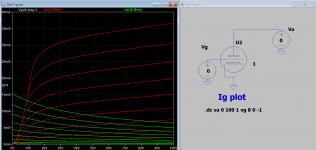
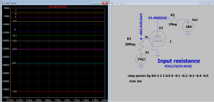
Ayumi is the only one that models grid current Ig/Ia plot ok but for some reasons it fails to plot Vg/Ig which is the input impedance of the tube. Not sure which brand 12ax7ay it referred to in the model so I cannot verify the accuracy of the plots, but verify quite well against circuits around on the net.
Using this data as a hint I built Mazda 12ax7s model, successfully plot input impedance curve for various grid bias voltage so see how it goes.
Code:
**** 12AX7_MAZ ** Advanced Grid Current **********************************
* Created on 05/24/2020 18:29 using paint_kit.jar 3.1
* [URL="http://www.dmitrynizh.com/tubeparams_image.htm"]www.dmitrynizh.com/tubeparams_image.htm[/URL]
* Plate Curves image file: 12ax7-maz.png
* Data source link: [URL]https://frank.pocnet.net/sheets/020/1/12AX7S.pdf[/URL]
*----------------------------------------------------------------------------------
.SUBCKT 12AX7_MAZ 1 2 3 ; Plate Grid Cathode
+ PARAMS: CCG=3P  CGP=1.4P CCP=1.9P
+ MU=100 KG1=2354.4 KP=771.4 KVB=63.48 VCT=0.7102 EX=1.658
+ VGOFF=-0.702 IGA=3.5E-4 IGB=0.096 IGC=47.36 IGEX=2
* Vp_MAX=500 Ip_MAX=3.5 Vg_step=0.5 Vg_start=1 Vg_count=14
* Rp=4000 Vg_ac=55 P_max=1.1 Vg_qui=-48 Vp_qui=300
* X_MIN=37 Y_MIN=14 X_SIZE=767 Y_SIZE=537 FSZ_X=1296 FSZ_Y=736 XYGrid=false
* showLoadLine=n showIp=y isDHT=n isPP=n isAsymPP=n showDissipLimit=y
* showIg1=y gridLevel2=y isInputSnapped=n
* XYProjections=n harmonicPlot=n dissipPlot=n
*----------------------------------------------------------------------------------
E1 7 0 VALUE={V(1,3)/KP*LOG(1+EXP(KP*(1/MU+(VCT+V(2,3))/SQRT(KVB+V(1,3)*V(1,3)))))}
RE1 7 0 1G  ; TO AVOID FLOATING NODES
G1 1 3 VALUE={(PWR(V(7),EX)+PWRS(V(7),EX))/KG1}
RCP 1 3 1G   ; TO AVOID FLOATING NODES
C1 2 3 {CCG} ; CATHODE-GRID
C2 2 1 {CGP} ; GRID=PLATE
C3 1 3 {CCP} ; CATHODE-PLATE
RE2 2 0 1G
EGC 8 0 VALUE={V(2,3)-VGOFF} ; POSITIVE GRID THRESHOLD
GG 2 3 VALUE={(IGA+IGB/(IGC+V(1,3)))*(MU/KG1)*(PWR(V(8),IGEX)+PWRS(V(8),IGEX))}
.ENDS
*$
Attachments
Last edited:
- Home
- Amplifiers
- Tubes / Valves
- Vacuum Tube SPICE Models